 RF
RFRadar Measurements and Duty Cycle for Optimal Performance
Advertisement
Radar systems rely on various measurements and metrics to operate effectively. One of the critical parameters is the radar duty cycle, which affects the radar’s average power and overall detection capability. This tutorial provides an overview of radar transmitter and receiver measurements.
The common tools used for radar maintenance and measurements are multimeters, spectrum analyzers, oscilloscopes, power meters, frequency counters, signal generators, crystal detectors, attenuators, etc.
Radar Transmitter Measurements
The radar transmitter measurements include transmitted Power and Stability, PW, PRF, Duty Cycle/Factor, Klystron Pulse, Klystron Current, Klystron RF Input Level, Transmitted frequency, Occupied BW, and VSWR. Let’s examine these radar transmitter measurement parameters one by one.
Transmitted Power
The transmitted power is measured with the help of a calibrated power meter. The value is calculated taking into consideration the loss of the cable as well as the duty cycle factor.
Where,
Loss will be the path loss between the output flange of the klystron and the RF transmitter monitor connector.
Power Stability
With a Pulse Width of 1 µsec and a PRF of 250Hz, the acceptable level for power stability is about +/-0.5 dB. For example, if the power output varies from -14.95dBm to -15.05dBm in a half-hour period, the difference in the variation of power here is 14.95 - (-15.05) = 0.1 dB. This is less than the acceptable level.
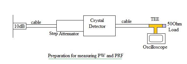
PW, PRF, Duty Cycle or Duty Factor
This measurement is carried out using an oscilloscope. If the oscilloscope is not capable of measuring high frequencies, then the arrangement as shown in the figure is used. A step attenuator and crystal detector are used for this purpose.
To measure PW, we need 3dB attenuation, as it is the width at half power points. Similarly, PRF and the duty factor are measured using an oscilloscope.
As mentioned, radar measurements include factors like pulse width, pulse repetition frequency (PRF), and range. These parameters play a role in determining the radar’s range resolution, maximum detectable range, and target identification accuracy. Understanding these metrics is essential for configuring radar systems to meet specific operational requirements.
- Pulse Width: The duration of the radar pulse, influencing range resolution.
- Pulse Repetition Frequency (PRF): The number of pulses transmitted per second, affecting maximum range and detection.
- Radar Duty Cycle: Defined as the ratio of the pulse width to the pulse repetition period, it measures the proportion of time the radar is transmitting. A high duty cycle indicates a radar with high average power, useful for detecting distant or low-reflective targets.
Klystron Pulse, Klystron current
The klystron pulse waveform is measured at the output of the transmitter front panel using an oscilloscope. The klystron current is calculated by multiplying the oscilloscope value with 10. For example, if the oscilloscope reading for the max. peak is 1.2V, then the current is 12Amp.
Klystron RF input level
In this test, the RF drive power level and RF frequency are measured to check whether they are within the normal range or not. The frequency should be about 5625MHz. The same is measured using either a spectrum analyzer or a frequency counter.
Occupied Bandwidth
Occupied BW is the width of the band over which the emitted mean power is about 99% of the total mean power. The difference between the lower and upper frequency points is referred to as occupied BW.
VSWR measurement
It is the measure of how much power is transmitted and how much is reflected. Return loss, in general, = Forward power - Reflected power.
Radar receiver measurements
The radar receiver is a very critical part of a radar system as it has to detect and amplify the received weak signal from the antenna. The radar receiver measurements include STALO level measurement, COHO level measurement, receiver Gain, Minimum Detectable Signal (MDS), Dynamic range, intensity check, velocity check, etc.
STALO Level Measurement
Radar usually will have different STALO frequencies and power levels. The main aim is to determine weak signal receiver power. A digital power meter is used for this purpose.
COHO Level Measurement
COHO stands for COHerent Oscillator. It has a frequency of about 30MHz.
Receiver Gain
The radar transmitter is kept off, and the signal generator frequency is set equal to the radar receiver for this test.
Similarly, the dynamic range is calculated by finding MDS and saturated input points.
Tx IF Out and Exciter RF
Transmitter IF OUT is a pulse modulated COHO output which is up-converted to RF level. The Exciter RF signal is passed to the klystron. A spectrum analyzer is used for this purpose.
Intensity Check measurement
It is done to see how well the system performs the processing of the reflected signal after coming into the LNA through the Signal Processor.
Velocity Accuracy
A velocity accuracy check measurement is done to see how well the system calculates the velocity of an echo.
Conclusion
Comprehending radar measurements and duty cycle helps in designing radars with the desired power, range, and resolution for varied applications, from navigation to target tracking.
Advertisement


