 RF
RFSigFox Uplink and Downlink Data Call Flow
Advertisement
SigFox, a leading LPWAN (Low-Power Wide-Area Network) technology, enables efficient IoT communication using minimal power. Understanding the uplink and downlink data call flow procedure is crucial for optimizing SigFox device communication. This article outlines the step-by-step process of message flow between SigFox devices, base stations, and the backend, detailing the key elements involved in data transmission.
The uplink refers to data transmission from the LEP (LTN End Point) to the LAP (LTN Access Point), while the downlink is the reverse, from LAP to LEP.
About Sigfox
Sigfox is a low-power, low-data-rate wide area networking wireless technology. Due to its lower throughput, the system is also known as LTN (Low Throughput Network). It operates in the ISM (Industrial, Scientific, and Medical) bands, specifically 868 and 915 MHz.
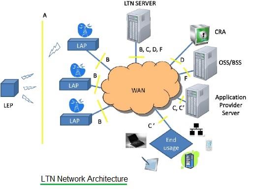
There are four basic entities in the Sigfox wireless system:
- LEP (LTN End Point or objects): These are the Sigfox devices themselves.
- LAP (LTN Access Point or Base Stations or Gateways): These receive and transmit Sigfox signals.
- WAN (e.g., Cloud): The wide area network connecting the LAPs to the backend servers.
- Servers: Backend servers that process and route the data.
The flow of information through the Sigfox system is known as data flow. In order to send or receive data, a data call needs to be established. The transmission of data from the LEP to the LAP direction is known as the uplink, and the transmission of data from the LAP to the LEP direction is known as the downlink. Based on this, there is an uplink data call and a downlink data call.
Sigfox Uplink Data Flow
Following are the steps associated with the Sigfox uplink data flow:
- LEP Transmission: Whenever there is information to be sent, the LEP (LTN End Point or Sigfox object) simply occupies the RF channel and transmits over the air.
- LAP Reception: The information is received by one or multiple LAPs (or base stations).
- Packet Processing: Each LAP down-converts, demodulates, and decodes the received RF packet.
- Data Forwarding: Each LAP forwards the decoded message to the LTN server using a secured IP link.
- Server Processing: The LTN Server performs authentication and authorization of the message and pushes the message to the application provider server. Standard APIs are used in order to push or pull messages to/from the application server.
This completes the Sigfox uplink data call.
Sigfox Downlink Data Flow
Following are the steps associated with the Sigfox downlink data flow:
- LEP Listen Window: In order to receive data in the downlink, the LEP opens a fixed window after an uplink transmission.
- LAP Transmission: This window is used by the LAPs to send the information to the respective LEP intending to receive information.
- Application Server to LTN Server: The application server transmits the message to the LTN server.
- LTN Server to LAP: The LTN server forwards this message to the appropriate LAP.
- LAP to LEP Transmission: The LAP transmits the message to the LEP in the time slot opened by it (i.e., LEP).
This completes the Sigfox downlink data call.
References
- ETSI GS LTN 002 (Low Throughput Networks) document.
Conclusion
SigFox’s simplified uplink and downlink data call flow is designed for low-power, cost-effective IoT communication. By understanding these procedures, developers can enhance device performance and tailor applications to suit specific IoT needs.
Advertisement


