 RF
RFSDH Frame Structure: A Comprehensive Tutorial
Advertisement
This tutorial covers the SDH (Synchronous Digital Hierarchy) frame structure, explaining the STS-1 (Synchronous Transport Signal-1) SONET/SDH frame in detail. This includes the concept of interleaving, as well as the transport overhead and payload overhead sections of the SDH frame.
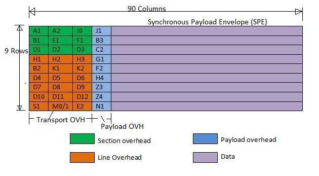
The figure illustrates a basic SONET STS-1 frame, which consists of 9 rows and 90 columns.
A SONET frame is composed of 810 octets (bytes). Transmission happens row by row, from left to right and top to bottom. Bits are transmitted serially. The STS-1 frame of SDH includes the section overhead, transport overhead, payload overhead, and the data payload.
The frame begins with a fixed A1/A2 bit pattern, 0xf628, used for bit/octet synchronization. SONET/SDH is considered octet synchronous. The first three columns of the SONET frame are the transport overhead. The subsequent 87 columns are the Synchronous Payload Envelope (SPE), which includes the payload overhead. The STS-1 data rate is approximately 51.84 Mbps. This rate is achieved because each SONET/SDH frame repeats every 125 microseconds.
STS stands for Synchronous Transport Signal.
STS-1, after scrambling, is referred to as OC-1 (Optical Carrier).
SDH/SONET Digital Rate Hierarchy
| SONET Rate Name | SDH Name | Line Rate (Mbps) | Synchronous Payload Envelope Rate (Mbps) | Transport Overhead Rate (Mbps) |
|---|---|---|---|---|
| STS-1 | None | 51.84 | 50.112 | 1.728 |
| STS-3 | STM-1 | 155.52 | 150.336 | 5.184 |
| STS-12 | STM-4 | 622.08 | 601.344 | 20.736 |
| STS-48 | STM-16 | 2488.32 | 2405.376 | 84.672 |
| STS-192 | STM-64 | 9953.28 | 9621.504 | 331.776 |
| STS-768 | STM-256 | 39813.12 | 38486.016 | 1327.104 |
Interleaving in SONET/SDH
An STS-3 frame is created by interleaving three STS-1 frames. The interleaving is done at the octet level; that is, the A1 octet from the first, second, and third STS-1 frames is taken sequentially, followed by the A2 octets from all three frames, and so on.
Transport Overhead
- Framing octets (A1, A2): These two octets,
A1 = 0xf6andA2 = 0x28(hexadecimal), are used to identify the start of the SDH frame. - Section Trace (J0): It is used to allow connected sections to verify whether the connection is still active and properly terminated.
- Parity (B1): This octet is used by the receiver for bit error rate (BER) estimation. Being 8 bits, it allows for 8 parity calculations.
- Order Wire (E1): Originally used by technicians during system installation for testing, but is not in common use today.
- Section User Channel (F1): Used by the network service provider to carry information from section to section within the line.
- Section Data Communication Channel (D1, D2, D3): These octets create a 192 kbps communication channel for sending administrative messages. Used for maintenance, control, alarms, monitoring, administration, and other communication needs between section-terminating equipment.
- Pointers and Pointer Action (H1, H2, H3): Used to point to the payload (SPE). They include flags to indicate payload location changes.
- Line Parity (B2): The B2 octet is used for bit error rate estimation.
- Automatic Protection Switching (APS) channel (K1, K2): Used for APS signaling between line-level entities. APS stands for Automatic Protection Switching.
- Line Data Communications Channel (D4-D12): D4 to D12 octets form a communication channel to send administrative messages, operating as a 576 kbps channel. Used for line data communication and for maintenance, control, monitoring, administration, alarms, as well as communication needs between line terminating entities.
- Synchronization messaging (S1): Transports synchronization status messages and is defined for STS-1 of the STS-N signal. Bits 5 to 8 are used.
- STS-1 REI (M0): Sends the number of errors detected by B octets back to the transmitter, aiding in understanding line and receiver status.
- STS-N REI (M1): Same function as M0.
- Order Wire (E2): Same function as E1.
Payload Overhead
The first column in the Synchronous Payload Envelope (SPE) is the Payload Overhead (POH). It includes: Path Trace (J1), Path BIP-8 (B3), STS Path Signal Label (C2), Path Status (G1), Path user channel (F2), Multi-frame indicator (H4), growth octets (Z3, Z4), and N1 fields.
- Path Trace (J1): Helps the two ends verify the connection status (active or not) and check if it’s connected with the correct terminations. It transmits the STS path Access Point Identifier repetitively, allowing the path receiving terminal to verify its continuous connection with the intended transmitter. A 64-byte frame is used.
- Path BIP-8 (B3): Used by the receiver for BER estimation. It’s calculated over all the bits of the previous STS SPE before scrambling.
- STS Path Signal Label (C2): Indicates the type of traffic carried in the payload part of the SDH frame.
- Path Status (G1): Used to convey path terminating status/performance back to the transmitter (Originating STS PTE). PTE stands for Path Terminating Equipment.
- Path user channel (F2): Used for user communication, similar to the F1 octet in the transport overhead.
- Multi-frame indicator (H4): Provides a generalized multi-frame indicator for the payloads. Primarily used for VT-structured payloads and to support virtual concatenation of STS-1 SPEs.
- Growth octets (Z3, Z4): Reserved for future use.
- N1 fields: Used to allocate support for tandem connection maintenance and tandem connection data link.
Advertisement


