Modbus Protocol Tutorial: Frame Formats for RTU, ASCII and TCP
Advertisement
Modbus is a communication protocol developed by Modicon (now Schneider Electric) in 1979 for use with its programmable logic controllers (PLCs). It has become a standard communication protocol and is widely used in industrial applications for connecting electronic devices.
Modbus enables communication between many devices connected to the same network, including sensors, instruments, and other devices. It is known for its simplicity and reliability.
Let’s explore the workings of the Modbus protocol, including its various frame formats for RTU, ASCII, and TCP communication with examples.
What is Modbus Protocol?
Introduction: “Modbus” is a trademark of Modicon Inc., which maintains the standard. It’s an application layer protocol based on a client/server architecture between devices connected on different types of buses or networks.
This Modbus protocol is frequently used in SCADA (Supervisory Control and Data Acquisition) systems for network communication between devices.
The Modbus protocol runs on top of RS232, RS422, and RS485 serial communication standards. There’s also a specification for Modbus/TCP, designed for IP-based link layers.
Many protocols exist for industrial automation and metering, and Modbus uses a query/response model. The following figure illustrates the structure of “Query messages” and “Response messages,” showing their constituent fields.
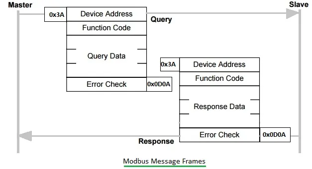
- As shown, both query and response messages consist of start (0x3A) and end (0x0D0A) delimiters.
- Query messages include fields such as device address, function code, query data, and error check.
- Response messages contain fields for device address, function code, response data, and error check.
How Modbus Works
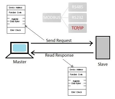
Modbus operates on a master-slave (or client-server) model. A master device initiates communication with a slave device, requesting information or sending commands. The slave device then responds to the master’s request, providing the requested data or acknowledging the command.
Modbus architecture gives the master complete control over information flow, which is a significant advantage over older multidrop networks using RS422/RS485. Modbus supports various transmission modes, including Modbus RTU, Modbus ASCII, and Modbus TCP.
-
As illustrated in the figure, a Modbus request message is a layered set of data. Controllers can be configured to communicate on standard Modbus networks using either ASCII or RTU transmission modes. Users select the desired mode, along with serial port communication parameters (baud rate, parity mode, etc.), during controller configuration. The mode and serial parameters must be consistent for all devices on a Modbus network.
-
The choice between ASCII or RTU (Remote Terminal Unit) mode applies only to standard Modbus networks. It defines the bit contents of message fields transmitted serially on those networks and determines how information will be packed into the message fields and decoded.
-
When controllers communicate on a Modbus network using ASCII mode, each eight-bit byte in a message is sent as two ASCII characters. The primary advantage of this mode is that it allows time intervals of up to one second between characters without causing an error.
-
In RTU mode, each eight-bit byte in a message contains two four-bit hexadecimal characters. The main advantage is that its greater character density allows better data throughput than ASCII for the same baud rate. Each message must be transmitted in a continuous stream.
-
In either serial transmission mode (ASCII or RTU), a Modbus message is placed by the transmitting device into a frame that has a known beginning and ending point. This allows receiving devices to begin at the start of the message, read the address portion to determine which device is addressed, and know when the message is completed. Partial messages can be detected, and errors can be flagged.
-
Modbus operates on a master-slave model, where one device initiates transactions (queries) that address individual slave devices or broadcast to all slaves. The slave device acts according to the received Modbus frame and responds if required, in the form of a “response frame.”
-
The transmission mode defines the framing and bit encoding of the messages to be transmitted on the Modbus network.
Modbus ASCII Frame
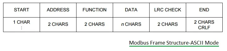
The figure shows the ASCII mode of a Modbus frame. In ASCII mode, each byte is encoded on the serial link as two ASCII characters. Each ASCII character is transmitted with 1 start bit, 7 data bits, zero or 1 parity bit, and one or two stop bits.
Modbus RTU Frame
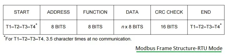
The figure depicts the RTU mode of a Modbus frame. In RTU (Remote Terminal Unit) mode, the message is transmitted in a continuous stream format. Each 8-bit byte is framed by 1 start bit, 8 data bits, 0 or 1 parity bit, and 1 or 2 stop bits. The message starts after a silent period of at least 3.5 character times.
Modbus Message Structure Fields
Let’s understand the major fields used in both ASCII and RTU modes.
-
Modbus Address: The Modbus message starts with an 8-bit target address, ranging from 0 to 247. Here, 0 is used as a broadcast address, and the rest are unique device addresses.
-
Modbus Functions: The function code consists of 2 characters (in ASCII mode) or 8 bits (in RTU mode), taking a value from 1 to 255. The code is selected based on the application profile.
-
Modbus Data Field: This field conveys application-level information as required by different Modbus functions. If the function involves variable-sized data, it begins with a “byte count” in this position.
-
Modbus Error Check Field: This field is used for error detection and is also known as the “Checksum.”
Modbus TCP Frame
Unlike RS232 and RS485, Modbus TCP uses the TCP/IP protocol to carry Modbus messages. The following figure shows the mapping of Modbus protocol within the TCP/IP and OSI protocol stacks.
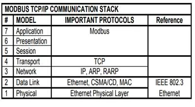
-
Modbus TCP provides TCP/IP access to Modbus functionality.
-
Each Modbus request/response is sent over a TCP connection established between the master and the slave, using the well-known port 502.
-
The TCP connection can be reused for multiple query/response exchanges.
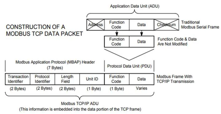
- The byte content of the Modbus request/response frames (without framing start-stop-parity bits specific to the serial physical layer) is simply transported over the TCP connection in big-endian order. The only addition in Modbus TCP is a seven-byte message prefix.
Ref Ref 00 00 00 len unit
-
The “ref” bytes are simply copied by the slave from the request and can be used as a handle by the master. The length information in the message prefix allows proper reassembly of the Modbus message when it has been segmented into several IP packets.
-
The slave address has been renamed “unit identifier” and is contained in the “unit” field. The rest of the message conforms to the regular Modbus structure, but the error check fields may be omitted.
Profibus vs Modbus
The following table compares Profibus and Modbus with respect to various parameters.
| Features | Profibus | Modbus |
|---|---|---|
| Mode of operation | Operates in multi-master mode using RS485. | Operates on only single master mode using ASCII/RTU. |
| Use of ethernet | Cannot operate on ethernet, but Profinet operates on ethernet which is not the same as Profibus. | Can run on ethernet using TCP/IP protocols. |
| Physical medium | Twisted pair, fiber | Modbus does not define a physical medium; it defines message structure that can be used over any physical medium. However, Modbus RS485 is popular. |
| Speed of transmission | Operates at different speeds of transmission from 1.2 Kbps to 12 Mbps. | Modbus RS485 supports speeds of transmission up to 115 Kbps or up to 19.2 Kbps. |
| Distance coverage | 32 stations use Profibus for distances up to 1200 meters, while 2 stations communicate at 500 kbps for distances up to 400 meters. Low speed supports higher distances. | Modbus RS485 cable should be less than 700 meters. |
| Number of devices | Up to 126 devices (masters and slaves) can be connected on a single Profibus network. | Modbus master actually supports 247 slave devices. The number of slave devices connected is 32 due to RS485 protocol limitation. A repeater is used to support more. |
| Future use | Specialized sensor/actor fieldbus devices have increased their market penetration. | Simple protocol makes it popular as one of the main ethernet protocols in automation. Older versions are RS232, RS422, RS485, etc. |
| Application | Very robust; used to automate entire plants, especially with multiple vendors and equipment. | Simple; used to interface single controllers in point-to-point mode for small plant automation. |
Modbus Application Examples
The Modbus protocol can be implemented in various systems, such as RS485/RS422.
- Zigbee to Modbus RTU/TCP Gateway
- Real-time inventory control, such as pick to light, put to light, etc.
- Industrial automation
- Smart metering
Summary
Modbus is a versatile protocol that supports multiple transmission modes, each with its own frame format. Modbus RTU is efficient for serial communication, Modbus ASCII is easier to read and debug, and Modbus TCP integrates well with modern Ethernet networks. Each mode ensures reliable data exchange between master and slave devices, making Modbus a widely used standard in industrial automation and control systems.