4G LTE Tutorial: Basics, Architecture, Channels, and More
Advertisement
4G LTE (Long-Term Evolution) technology marks a significant leap in mobile communications, offering users high-speed data and seamless connectivity. LTE is widely recognized as a 4G technology. It evolved from earlier generations like 2G (GSM) and 3G (UMTS/HSPA) to meet the growing demand for higher data rates and enhanced Quality of Service (QoS).
An LTE network typically delivers data rates of about 100 Mbps in the downlink and around 50 Mbps in the uplink. It has become the cornerstone for most mobile networks globally, facilitating services like HD video streaming, VoIP (Voice over IP), and sophisticated web applications. With the introduction of LTE Advanced and LTE Pro, additional features such as carrier aggregation, MIMO (Multiple Input, Multiple Output), and improved spectral efficiency have been integrated.
This 4G tutorial delves into LTE’s basic principles, network architecture, channels, frequency bands, QoS, protocol stack, comparison with 2G/3G, advantages, and disadvantages.
LTE Terminology
- Evolved NodeB (eNodeB): LTE base station responsible for radio communication with user equipment (UE).
- User Equipment (UE): Any device that interacts with the LTE network (e.g., smartphones, tablets).
- Evolved Packet Core (EPC): Core network providing connectivity and managing data routing.
- Carrier Aggregation: A technique to boost bandwidth by combining multiple carriers.
- MIMO (Multiple Input, Multiple Output): Antenna technology designed to improve data throughput and reliability.
- PDN (Packet Data Network): External networks (e.g., the Internet) accessed through the EPC.
- QoS (Quality of Service): A framework ensuring consistent service delivery based on application requirements.
LTE Parameters
- Frequency Range: LTE operates on various frequency bands depending on the region, typically between 700 MHz and 2600 MHz.
- Bandwidth: LTE supports variable bandwidths of 1.4, 3, 5, 10, 15, and 20 MHz. This bandwidth flexibility allows LTE to adapt to different spectrum availabilities.
- Modulation: LTE uses OFDMA (Orthogonal Frequency Division Multiple Access) for downlink and SC-FDMA (Single Carrier-Frequency Division Multiple Access) for uplink. Modulation schemes like QPSK, 16-QAM, and 64-QAM are used to maximize spectral efficiency.
- Coding: Turbo coding serves as the channel coding scheme in LTE, ensuring error correction and data integrity.
- Data Rate: LTE offers peak data rates of up to 100 Mbps (DL) and 50 Mbps (UL) for a 20 MHz bandwidth.
LTE QoS
QoS in LTE is managed through bearers, which are logical data pipes that carry traffic between the UE and the EPC. Each bearer is associated with a QoS Class Identifier (QCI) that defines the priority and performance characteristics of the data flow. Key QoS parameters include:
- Latency: The time it takes for data to travel between endpoints. LTE aims for a latency of less than 10 ms for user-plane traffic.
- Jitter: Variations in packet delay that can negatively affect real-time services such as voice and video.
- Packet Loss: The percentage of data packets lost during transmission.
E-UTRA Frequency Bands
LTE operates on diverse frequency bands globally, identified by the E-UTRA band numbering scheme. Below are some prominent bands used worldwide. The air interface between the LTE network and the UE uses these frequencies for communication. OFDMA modulation is used from the network to the UE air interface, and SC-FDMA is used from the UE to the network air interface.
| LTE Band Number | Frequency Range (MHz) | Region |
|---|---|---|
| Band 1 | 1920 - 1980 / 2110 - 2170 | Asia, Europe |
| Band 3 | 1710 - 1785 / 1805 - 1880 | Asia, Europe |
| Band 7 | 2500 - 2570 / 2620 - 2690 | Worldwide |
| Band 20 | 832 - 862 / 791 - 821 | Europe |
| Band 40 | 2300 - 2400 | India, Asia |
LTE Architecture
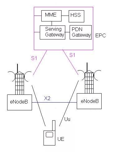
As shown in the figure, LTE SAE (System Architecture Evolution) consists of the UE, eNodeB, and EPC (evolved packet core). Various interfaces are designed between these entities, including Uu between the UE and eNodeB, X2 between two eNodeBs, and S1 between the EPC and eNodeB. The eNodeB incorporates functionalities of both the RNC and NodeB from previous UMTS architectures. LTE is entirely an IP-based network. The LTE architecture comprises the following network elements:
- LTE EUTRAN (Evolved Universal Terrestrial Radio)
- LTE Evolved Packet Core
-
LTE EUTRAN: It is a radio access network standard intended as a replacement for UMTS, HSDPA, and HSUPA. Unlike HSPA, LTE’s E-UTRA is an entirely new air interface system. It provides higher data rates, lower latency, and is optimized for packet data. EUTRAN (Evolved Universal Terrestrial Radio) consists of eNBs (Base stations). EUTRAN is responsible for complete radio management in LTE. When a UE is powered on, the eNB manages Radio Resource Management, i.e., it handles radio bearer control, radio admission control, and allocation of uplink and downlink resources to the UE. When a packet from a UE arrives at the eNB, the eNB compresses the IP header and encrypts the data stream. It is also responsible for adding a GTP-U header to the payload and sending it to the SGW. Before the data is transmitted, the control plane must be established. The eNB chooses an MME using the MME selection function. The QoS is managed by the eNB, as it is the only entity on the radio side. Other functionalities include scheduling and transmission of paging messages, broadcast messages, and bearer-level rate enforcements, all handled by the eNB.
-
LTE Evolved Packet Core (EPC): The LTE EPC includes the MME, SGW, PGW, HSS, and PCRF.
- MME (Mobility Management Entity): Manages session states, UE tracking, and authentication.
- SGW (Serving Gateway): Routes data between eNodeBs and the PDN.
- PGW (Packet Gateway): Manages IP allocation and connects the LTE network to external PDNs.
- HSS (Home Subscriber Server): Stores user profiles and performs authentication.
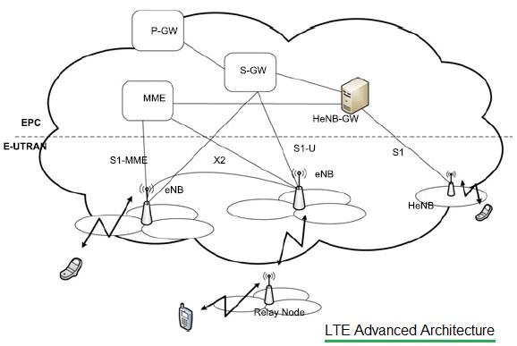
LTE Advanced architecture for E-UTRAN consists of P-GW, S-GW, MME, S1-MME, eNB, HeNB, HeNB-GW, Relay Node, etc. The LTE Advanced protocol stack comprises user and control planes for AS and NAS.
LTE Channels
The channels in an LTE system are categorized into logical, transport, and physical channels based on their functions.
- Logical Channels: Define the type of information transmitted, such as BCCH (Broadcast Control Channel) and DCCH (Dedicated Control Channel).
- Transport Channels: Specify how data is transferred, such as PCH (Paging Channel) and DL-SCH (Downlink Shared Channel).
- Physical Channels: Define the actual radio frequency resources used, such as PDSCH (Physical Downlink Shared Channel) and PUSCH (Physical Uplink Shared Channel).
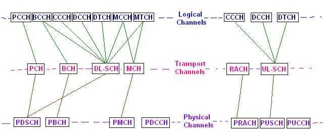
The downlink (eNodeB to UE) channels are PBCH, PDSCH, PDCCH, PMCH, PCH, etc. The uplink (UE to eNodeB) channels are PRACH, PUSCH, and PUCCH.
LTE Frame Structure
LTE frames have a duration of 10 ms and consist of 10 subframes, each containing two slots. LTE (Long-Term Evolution) supports two duplexing modes for radio communication: Frequency Division Duplex (FDD) and Time Division Duplex (TDD). The frame structure in LTE differs for each mode, depending on how uplink and downlink transmissions are separated.

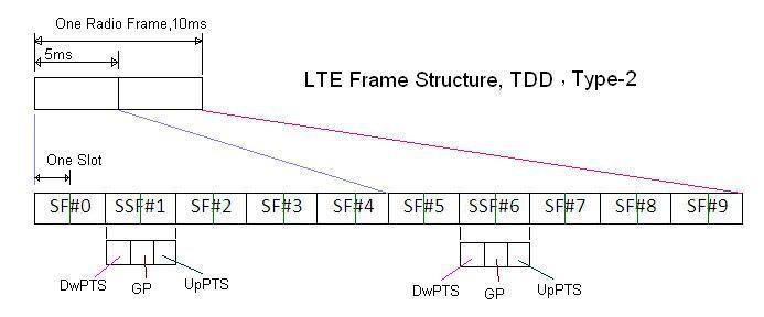
- In FDD mode, uplink and downlink transmissions occur simultaneously on separate frequency bands. This means communication is continuous and non-interfering.
- In TDD mode, uplink and downlink transmissions share the same frequency band but are separated in time. The frame is divided into time slots dedicated to either uplink or downlink transmission.
LTE Protocol Stack Layers
The LTE protocol stack is divided into two planes: the user plane and the control plane.
- User Plane: Handles the transfer of user data and is composed of PDCP (Packet Data Convergence Protocol), RLC (Radio Link Control), and MAC (Medium Access Control) layers.
- Control Plane: Manages control signaling and includes protocols such as RRC (Radio Resource Control), NAS (Non-Access Stratum), and S1AP (S1 Application Protocol).
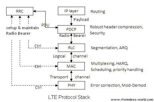
The LTE stack consists of different layers: Physical, MAC, RLC, PDCP, and RRC.
LTE Advantages and Disadvantages
Following are advantages of LTE technology :
- High data rates and low latency.
- Efficient use of bandwidth with support for carrier aggregation.
- Enhanced spectral efficiency and capacity.
- Seamless support for voice and multimedia services over IP (VoLTE).
Following are disadvantages of LTE :
- Higher deployment and infrastructure costs.
- Battery consumption is higher compared to 2G/3G.
- Spectrum fragmentation issues due to varied frequency bands.
Comparison with 2G/3G
The table below compares 4G LTE with its predecessor cellular technologies (2G GSM and 3G UMTS).
| Feature | 2G GSM | 3G UMTS | 4G LTE |
|---|---|---|---|
| Frequency Band | 900/1800 MHz | 2100 MHz | 700 MHz - 2600 MHz |
| Data Rate | Up to 384 kbps | Up to 42 Mbps | Up to 100 Mbps (DL) |
| Latency | >100 ms | 50 - 100 ms | < 10 ms |
| Modulation | GMSK | QPSK, 16-QAM | QPSK, 16-QAM, 64-QAM |
| Core Network | Circuit-Switched | Circuit/Packet-Switched | Packet-Switched |
| Voice Technology | Circuit-Switched | Circuit/VoIP | VoIP (VoLTE) |
| Handover | Hard Handover | Hard/Soft Handover | Seamless Handover |
Conclusion
4G LTE has revolutionized mobile communications by delivering faster data rates, low latency, and improved QoS. Its efficient use of spectrum and support for IP-based services have made it the preferred technology for network operators worldwide. While the evolution to 5G is underway, LTE remains a critical component of mobile networks, providing reliable connectivity and supporting advanced applications such as IoT and smart cities. This LTE tutorial is very useful for beginners who would like to start learning LTE fundamentals.
Advertisement
 RF
RF


