 RF
RF4G Architecture: LTE Network Elements and Interfaces
Advertisement
The 4G LTE network architecture forms the backbone of modern mobile communication, enabling high-speed data transfer and seamless connectivity. It consists of multiple network elements and interfaces that work in harmony to provide efficient voice, video, and data services. This tutorial delves into the 4G architecture diagram, explaining the roles of LTE network elements including the eNodeB, MME, SGW, PGW, and various interfaces that facilitate communication between them. Understanding the architecture is essential for grasping how data flows through the LTE network and how services are delivered to end users.
LTE Architecture
The LTE (Long-Term Evolution) architecture is designed to provide high-speed data, low latency, and seamless connectivity for modern mobile communication systems. It includes several core network elements and interfaces that work together to support a variety of services and applications.
Below are the main functions and roles of key components in the LTE network architecture.
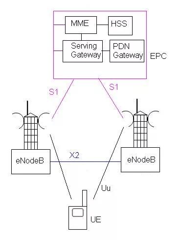
As shown in the diagram, LTE SAE (System Architecture Evolution) consists of UE, eNodeB and EPC(evolved packet core). Various interfaces are designed between these entities which include Uu between UE and eNodeB, X2 between two eNodeB, S1 between EPC and eNodeB. eNodeB has functionalities of both RNC and NodeB as per previous UMTS architecture.
LTE is completely IP based network. The basic architecture contains the following network elements.
- LTE EUTRAN (Evolved Universal Terrestrial Radio)
- LTE Evolved Packet Core.
1. LTE EUTRAN
It is a radio access network standard meant to be a replacement of the UMTS, HSDPA and HSUPA . Unlike HSPA, LTE’s E-UTRA is an entirely new air interface system. It provides higher data rates, lower latency and is optimized for packet data.
EUTRAN (Evolved Universal Terrestrial Radio) consists of eNB (Base station). EUTRAN is responsible for complete radio management in LTE. When UE powered is on, eNB is responsible for Radio Resource Management, i.e. it shall do the radio bearer control, radio admission control, allocation of uplink and downlink to UE etc. When a packet from UE arrives to eNB, eNB shall compress the IP header and encrypt the data stream. It is also responsible for adding a GTP-U header to the payload and sending it to the SGW.
Before the data is actually transmitted the control plane has to be established. eNB is responsible for choosing a MME using MME selection function. The QoS is taken care by eNB as the eNB is only entity on radio. Other functionalities include scheduling and transmission of paging messages, broadcast messages, and bearer level rate enforcements also done by eNB.
2. LTE Evolved Packet Core (EPC)
The LTE EPC architecture consists of MME, SGW, PGW, HSS and PCRF.
2.1 Mobility Management Entity (MME)
The MME is a control entity. It is responsible for all the control plane operations. All the NAS signaling originates at UE and terminates in MME. MME is also responsible for tracking area list management, selection of PGW/SGW and also selection of other MME during handovers. MME is also responsible for SGSN (Serving GPRS Support Node) selection during LTE to 2G/3G handovers. The UE is also authenticated by MME. MME is also responsible for bearer management functions including establishment of dedicated bearers for all signaling traffic flow.
2.2 Serving Gateway (SGW)
Serving gateway terminates the interface towards EUTRAN. For each UE there is a single Serving GW associated with EPS at a given point of time. SGW acts as a local mobility entity for inter eNB handovers. It also acts a mobility anchor for inter 3GPP mobility. SGW is responsible for packet routing and forwarding, buffering the downlink packets. As eNB is responsible for uplink packet marking, SGW is responsible for downlink packet marking.
2.3 PDN Gateway (PGW)
PGW terminates SGi interface towards the PDN. PGW is responsible for all the IP packet based operations such as deep packet inspection, UE IP address allocation, Transport level packet marking in uplink and downlink, accounting etc. PGW contacts PCRF to determine the QoS for bearers. It is also responsible for UL and DL rate enforcement.
2.4 Home Subscriber Server (HSS)
The HSS is a central database that contains user-related and subscription-related information. The functions of the HSS include functionalities such as mobility management, call and session establishment support, user authentication and access authorization. It also holds information about the PDNs to which the user can connect. In addition the HSS holds dynamic information such as the identity of the MME to which the user is currently attached or registered. The HSS may also integrate the authentication center (AUC), which generates the vectors for authentication and security keys.
2.5 Policy Control and Charging Rules Function (PCRF)
The PCRF is responsible for policy control decision-making as well as for controlling the flow-based charging functionalities in the Policy Control Enforcement Function (PCEF), which resides in the P-GW. The PCRF provides the QoS authorization (QoS class identifier and bit rates) that decides how a certain data flow will be treated in the PCEF and ensures that this is in accordance with the user’s subscription profile.
LTE Advanced Architecture
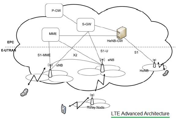
LTE Advanced architecture for E-UTRAN consists of P-GW, S-GW, MME, S1-MME, eNB, HeNB, HeNB-GW, Relay Node etc. LTE Advanced protocol stack consists of user plane and control plane for AS and NAS.
Benefits of 4G Architecture
The network architecture of 4G LTE is specifically designed to support a wide range of applications, provide efficient data handling, and deliver a superior user experience. Some of the key benefits are as follows.
- High Data Rates and Throughput: LTE supports peak data rates up to 100 Mbps in the downlink and 50 Mbps in the uplink, providing faster downloads and smoother streaming.
- Low Latency: The optimized design of the LTE core network reduces the latency to less than 10 milliseconds for user plane data, enabling real-time applications like VoIP and gaming.
- Efficient Spectrum Utilization: Advanced modulation schemes, carrier aggregation, and scalable bandwidth options ensure that LTE networks use spectrum resources efficiently, providing enhanced capacity and coverage.
- Seamless Mobility and Handover: LTE architecture ensures uninterrupted service when users move between cells or switch between LTE and other networks, minimizing dropped calls and lost connections.
- Quality of Service (QoS) Management: The architecture supports different QoS classes, ensuring that critical applications like emergency calls or video streaming receive prioritized treatment over less demanding services.
- Scalability and Flexibility: LTE can be deployed in various frequency bands and supports multiple deployment scenarios (macro, small cell, and heterogeneous networks), making it adaptable to different geographical and market needs.
- Support for Future Technologies: It serves as a foundation for advanced technologies such as LTE-Advanced, VoLTE, and IoT applications, ensuring long-term relevance and sustainability.
Conclusion
The 4G LTE architecture is a testament to the evolution of mobile networks, with its well-defined elements and interfaces ensuring robust performance and scalability. By understanding the architecture diagram, one can appreciate how LTE networks manage to deliver high-speed connectivity and low latency services. As mobile communication continues to evolve, a solid grasp of 4G architecture will remain essential for telecom professionals and learners alike.
Advertisement


