LTE Physical Layer: eNodeB and UE
Advertisement
This article describes the LTE physical layer, focusing on the transmitter modules in both the eNodeB (base station) and UE (user equipment) as per the LTE standard. The processing of the PDSCH channel through the LTE physical layer modules is detailed below.
Introduction
The physical layer (PHY) is responsible for carrying information from the upper layers. It acts as an interface between the MAC layer (Layer 2) and the RF (Radio Frequency) transceiver. The PHY layer resides at Layer 1 of the OSI stack and uses either wired or wireless mediums to transport the upper layer information.
Common functions of the PHY layer include:
- Converting the MAC layer format into a format suitable for the transmission medium.
- Adding FEC (Forward Error Correction) to enable error correction at the receiver.
- Performing modulation and demodulation at the transmitter and receiver ends, respectively.
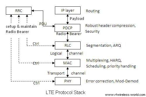
In LTE, various MAC layer frames exist in the downlink (PDSCH, PDCCH, PBCH) and uplink (PRACH, PUSCH, PUCCH). The physical layer processes these channels.
LTE Physical Layer eNodeB Transmitter
The following figure illustrates the LTE physical layer transmitter within the eNodeB (LTE base station). The LTE eNodeB is similar to the base stations found in other technologies like WiMAX and GSM.
The eNodeB physical layer includes modules for channel coding, rate matching, scrambling, mapping, layer mapping, precoding, resource element mapping, and OFDM modulation. A CRC (Cyclic Redundancy Check) is appended to the data received from the MAC layer before it is processed by the PHY layer.
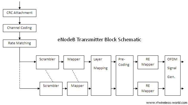
Let’s examine the LTE physical layer using the example of the Downlink Shared Channel (DL-SCH). As depicted in the figure for the eNodeB transmitter, upper layer data, in the form of a transport block, serves as input to the physical layer.
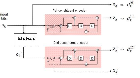
First, the transport block passes through a CRC encoder, employing a 24-bit CRC method. If the number of bits exceeds 6144, the block is divided into smaller blocks. These blocks are then Turbo coded. Turbo coding is a concatenated coding technique consisting of two convolutional encoders with interleaving between them. Rate matching acts as a rate coordinator between preceding and succeeding blocks, utilizing a buffer. QAM (Quadrature Amplitude Modulation) is used for modulation before the data is passed through an OFDM modulator.
The DL-SCH channel processing is visualized below:

CRC (Cyclic Redundancy Check)
A CRC is used for error detection in transport blocks. The entire transport block is utilized to calculate the CRC parity bits. The transport block is divided by a cyclic generator polynomial to generate 24 parity bits, which are then appended to the end of the transport block. The polynomial is as follows:
Segmentation and 2nd CRC
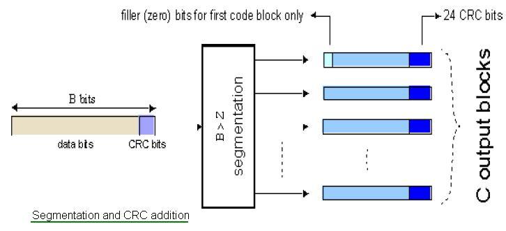
If the input block size is greater than 6144 bits, it is split into smaller blocks. CRC is then performed again, and redundant parity bits are appended to each resulting smaller block. Additionally, filler bits are added so the code block sizes match a set of valid block sizes input to the turbo code.
Turbo Coding
The constituent encoders used are convolutional encoders. The input to the first constituent encoder is the input bitstream to the turbo coding block. The input to the second constituent encoder is the output of the QPP interleaver, which is a permuted version of the input sequence.
Rate Matching and Modulation
The rate matching block creates an output bitstream with a desired code rate. The rate matching algorithm is capable of producing any arbitrary rate. The bit streams from the turbo encoder are interleaved, followed by bit collection to create a circular buffer. Bits are selected and punctured from the buffer to create an output bitstream with the desired code rate.
Physical Channels: Actual Transmission
Each physical channel corresponds to a set of resource elements in the time-frequency grid that carry information from higher layers. The basic entities that make up a physical channel are resource elements and resource blocks. A resource element is a single subcarrier over one OFDM symbol, and typically carries one (or two with spatial multiplexing) modulated symbol(s). A resource block is a collection of resource elements and, in the frequency domain, represents the smallest quanta of resources that can be allocated.
The transport channels need to be mapped into actual physical channels. The PDSCH channel carries user data originating from the higher layer and is associated with the DL-SCH. It involves various steps, such as scrambling, modulation mapping, layer mapping, precoding, resource mapping, and OFDM modulation.

As shown in the figure:
-
Scrambling: Produces a block of scrambled bits from the input bits according to the following relation:
Where denotes the scrambled bits, denotes the input bits, and denotes the scrambling sequence.
-
Modulation: Maps the bit values of input to complex modulation symbols with the specified modulation scheme. The modulation schemes for the PDSCH are QPSK (Quadrature Phase Shift Keying), 16QAM (Quadrature Amplitude Modulation), and 64QAM (Quadrature Amplitude Modulation).
-
Layer Mapper: Splits the data sequence into a number of layers.
-
Precoding: Used for transmission in multi-antenna wireless communications. In conventional single-stream beamforming, the same signal is emitted from each of the transmit antennas with appropriate weighting (phase and gain) to maximize the signal power at the receiver output.
-
Resource Mapping: Maps the actual data symbols, reference signal symbols, and control information symbols into a specific resource element in the resource grid.
LTE Phy Layer UE Transmitter
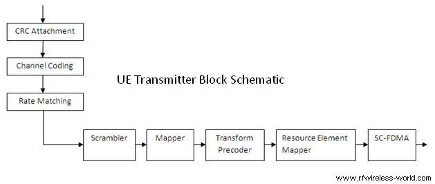
The figure above depicts the LTE physical layer modules in the UE (User Equipment) transmitter section. The LTE UE is similar to the subscriber station of other technologies like WiMAX and GSM. It includes channel coding, rate matching, scrambling, mapping, transform precoding, resource element mapping, and SC-FDMA. A CRC is appended to the data before it is passed to the PHY.
Advertisement
 RF
RF


