JESD204B Interface: A Comprehensive Tutorial
Advertisement
This tutorial provides a comprehensive overview of the JESD204B interface, covering its fundamental principles, features, and protocol layers. It aims to shed light on why JESD204B has become a popular choice for high-speed data transfer between ADCs/DACs and FPGAs/ASICs, surpassing older interfaces like LVDS and CMOS in terms of size, cost, and speed.
Originally introduced in 2006, the JESD204 standard has evolved through revisions, culminating in the robust and versatile JESD204B interface.
Introduction to JESD204B
The JESD204B interface is a high-speed serial data link designed for communication between data converters (ADCs/DACs) and receiver devices such as FPGAs or ASICs.

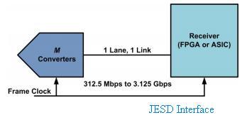
Figure 1: JESD Interface between Converters and FPGA/ASIC
As depicted in Figure 1, the JESD interface facilitates the transfer of data between converters and FPGAs/ASICs via a multi-gigabit serial link. The initial versions defined a single serial lane, but advancements have enabled multiple lanes between one or more converters and a receiver.
The rise of wireless technologies like LTE, LTE-Advanced, and 5G has fueled the adoption of JESD204B. These technologies rely on DSP blocks implemented on FPGAs or SoCs, which drive antenna arrays to generate multiple beams for individual subscriber handsets. This necessitates the transfer of hundreds of megabytes of data per second between FPGAs and data converters in both transmit and receive modes, making JESD204B an ideal solution.
Beyond wireless, JESD204B finds application in areas like:
- Software Defined Radios (SDRs)
- Medical Imaging Systems
- Radar Systems
- Secure Communications
JESD204A vs. JESD204B: Key Differences
While JESD204A laid the foundation, JESD204B introduced significant improvements. Let’s look at JESD204A first:

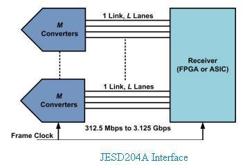
Figure 2: JESD204A Interface
JESD204A supported the following features:
- Maximum lane rate: 3.125 Gbps
- Support for multiple lanes
- Support for lane synchronization
- Support for multidevice synchronization
Now, let’s consider JESD204B:

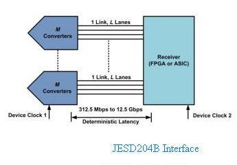
Figure 3: JESD204B Interface
JESD204B expands on the capabilities of JESD204A with the following enhancements:
- Maximum lane rate: 12.5 Gbps
- Support for multiple lanes, lane synchronization, and multidevice synchronization
- Support for deterministic latency
- Support for harmonic clocking
JESD204B Protocol Stack
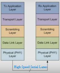
The JESD204B interface operates based on a layered protocol stack, as illustrated in Figure 4. Understanding this stack is key to understanding the operation of the interface.

Figure 4: JESD204B Protocol Stack
The stack comprises the following layers:
-
Physical Layer (PHY): This layer handles the physical transmission and reception of data. It is essentially the Serializer/Deserializer (SERDES) layer, responsible for transmitting and receiving characters at line-rate speeds. This includes drivers, receivers, and clock/data recovery mechanisms.
-
Data Link Layer: Responsible for encoding and decoding octets (optionally scrambled) to/from 10-bit characters. It manages the generation and detection of special control characters for lane alignment monitoring and maintenance.
-
Scrambling Layer: (Optional) This layer performs scrambling and de-scrambling of octets to mitigate EMI (electromagnetic interference) by spreading spectral peaks.
-
Transport Layer: This layer maps conversion samples to and from framed, non-scrambled octets.
-
Application Layer: This is the highest layer, responsible for handling specific application requirements at both the transmit and receive ends.
Advertisement
 RF
RF

