 RF
RF802.11ac WLAN Physical Layer Overview
Advertisement
This page provides an overview of the 802.11ac physical layer.
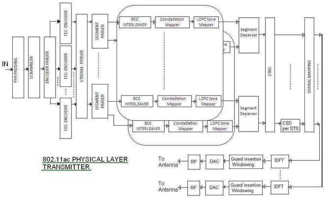
Figure: 802.11ac single user transmitter block diagram
As illustrated, the 802.11ac physical layer consists of these modules:
- PHY layer padding to the MAC frame.
- Scrambler
- Forward Error Correction
- Stream parser
- Segment parser
- Convolutional code interleaver
- Data mapping
- LDPC tone mapping
- Segment deparsing
- Space time block coding
- Pilot carrier insertion and cyclic shift diversity
- Spatial mapping
- Inverse Fourier Transform
- Guard insertion and windowing
- Preamble construction and frame formation
- ADC and RF Up conversion
The diagram shows that the 802.11ac transmitter supports both single-user and multiple-user modes. The MAC frame from the MAC layer serves as the input to this physical layer. Let’s examine the flow of information through the 802.11ac physical layer chain.
PHY Padding
First, a service field is generated and appended to the start of the data field. Padding is added to ensure the frame’s length matches the requirements for filling a complete symbol boundary.
Scrambling and FEC Encoding
Scrambling, implemented using shift registers and EX-OR gates, eliminates long sequences of 1s. The data then undergoes either convolutional encoding, LDPC encoding, or BCC encoding. Puncturing is applied to the encoded data to achieve higher and varied data rates.
Stream Parser
The stream parser processes the encoder output, dividing the encoded bits into multiple streams. These streams are referred to as spatial streams and are fed into the interleaver.
Segment Parser
In 160 MHz and dual 80 MHz bandwidth transmissions, the data is mapped onto two 80 MHz frequency segments prior to interleaving. Segment parsing is not applied to 20, 40, and 80 MHz bandwidths.
Convolutional Code Interleaver
During transmission, radio channel conditions can cause consecutive data bits to be affected. Interleaving disperses these consecutive bits across different subcarriers, making bit error correction easier.
Data Mapping
BPSK, QPSK, 16QAM, 64QAM, and 256QAM are used for data constellation mapping. BPSK maps one bit per carrier, QPSK maps two bits, and so on.
LDPC Tone Mapping
The constellation points are mapped to OFDM subcarriers with sufficient separation, functioning similarly to an interleaver. For example, in a 40 MHz scenario, two constellation points are separated by approximately 6 subcarriers.
Segment Deparsing
For 160 MHz bandwidth, the segment deparser combines two frequency segments, optimizing them for transmission.
Space Time Block Coding
This is an optional implementation feature. It transforms one stream into multiple streams for transmission across multiple antennas, increasing redundancy. Spatial streams are converted into space-time streams.
Pilot Carrier Insertion and Cyclic Shift Diversity
Pilot subcarriers are inserted, and a suitable symbol is formed according to the table below, based on the operating bandwidth. These pilot subcarriers are used for channel estimation and equalization. Each space-time stream is assigned a unique phase shift, facilitating their identification at the receiver.
Spatial Mapping
Spatial mapping maps space-time streams onto the transmit chains. In beamforming, space-time streams are shaped in a specific direction to concentrate energy.
Inverse Fourier Transform
The Inverse Fourier Transform (IFFT) converts frequency domain data into time domain data. FFT sizes of 64, 128, 256, and 512 are used for 20, 40, 80, and 160 MHz bandwidths, respectively.
Guard Insertion and Windowing
A guard interval is inserted at the beginning of the symbol, and the symbol is windowed. This helps to mitigate delay spread and limit the spectrum.
Preamble Construction and Frame Formation
A VHT preamble is created and appended to the frame. The preamble assists in channel estimation and front-end synchronization.
ADC and RF Up Conversion
The digital data is converted to analog data and then upconverted to the RF frequency.
Subcarriers in 11ac
| 11ac Bandwidth | Subcarrier range | Pilot subcarriers | Total subcarriers, data subcarriers |
|---|---|---|---|
| 20 MHz | -28 to -1 and +1 to +28 | -21,-7,+7,+21 | 56 total, 52 data |
| 40 MHz | -58 to -2 and +2 to +58 | -53,-25,-11, +11,+25,+53 | 114 total, 108 data |
| 80 MHz | -122 to -2 and +2 to +122 | -103,-75,-39,-11, +11,+39,+75,+103 | 242 total, 234 data |
| 160 MHz | -250 to -130,-126 to -6, +6 to +126, +130 to +250 | -231,-203,-167,-139,-117, -89,-53,-25,+25,+53,+89, +117,+139,+167,+203,+231 | 484 total, 468 data |
Advertisement


