 RF
RFDominant Mode in Waveguides: Rectangular & Circular Explained
Advertisement
Introduction
Waveguides are structures that efficiently guide electromagnetic waves from one point to another, and they’re frequently used in communication and radar systems. The dominant mode is the mode of wave propagation with the lowest cutoff frequency in a waveguide, making it the most efficiently transmitted.
In rectangular and circular waveguides, the dominant modes are different due to their distinct geometries. This article explains the concept of the dominant mode, its significance in waveguide design, and the specific modes for rectangular and circular waveguides.
Dominant Mode in Rectangular Waveguide
The generic cutoff wavelength equation for a rectangular waveguide is defined as follows: In the equation, m = number of half-waves along the broad side dimension, and n = number of half-waves along the shorter side.
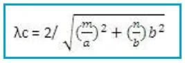
- For dominant mode TE10, m=1, n=0 and hence, .
Mode Designation: TE10 (Transverse Electric mode)
In the TE10 mode, the electric field is transverse to the direction of wave propagation, with no electric field component along the waveguide’s length.
Characteristics of TE10 Mode
-
Cutoff Frequency: It has the lowest cutoff frequency in rectangular waveguides, determined by the following formula:
-
Where,
cis the speed of light, andais the wider dimension of the waveguide. -
Field distribution: The electric field has a single half-wavelength variation across the wide dimension (‘a’) and is uniform along the narrow dimension (‘b’).
-
Applications: TE10 is widely used in microwave and radar due to its simplicity and efficiency.
Dominant Mode in Circular Waveguide
Mode Designation: TE11 (Transverse Electric mode)
- In the TE11 mode, both electric and magnetic fields have complex patterns due to the circular geometry, but no longitudinal electric field component exists.
Characteristics of TE11 Mode
-
It has the lowest cutoff frequency in circular waveguides, determined by the following equation. The cutoff frequency equation for a circular waveguide is defined below:
-
Where,
cis the speed of light within the waveguide andais the radius of the circular cross-section.-For dominant mode TE11,
-
Field Distribution: The electric field exhibits circular symmetry with azimuthal variations and no longitudinal component.
-
Applications: TE11 is common in satellite communication and high-power microwave systems.
Conclusion
The dominant mode in waveguides is critical for ensuring efficient and reliable electromagnetic wave propagation. In rectangular waveguides, the TE10 mode is dominant, while in circular waveguides, the TE11 mode often plays this role. Understanding these modes and their characteristics helps optimize waveguide performance across various applications, from telecommunications to industrial systems. By leveraging the properties of the dominant mode, engineers can achieve minimal signal loss and high transmission efficiency.
Advertisement


