Waveguide Couplers: Types, Principles, and Applications
Advertisement
Waveguide couplers are indispensable components in RF and microwave systems, playing a crucial role in power distribution and signal monitoring. This guide will explain their fundamental principles, various types, and significant applications within modern communication technologies.
The device that couples the Electro-Magnetic signal from the main path of a waveguide is called a waveguide directional coupler or simply a waveguide coupler. This functionality is required for monitoring purposes and to feed the signal to another location. Typically, a waveguide coupler will have four ports: input, output, coupled, and terminated.
The function of a waveguide coupler is similar to that of an RF directional coupler. For more detailed information, you can refer to resources on RF Directional Couplers. Figure 1 illustrates a typical waveguide coupler.
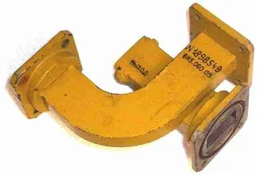 Figure 1: Waveguide Coupler
Working Principle:
Waveguide couplers operate by creating a controlled interaction between two waveguides or ports. This is achieved through apertures, slots, or loops. This intentional interaction allows a portion of the electromagnetic power traveling in one waveguide to be transferred to another. This enables signal sampling, monitoring, or splitting while maintaining high isolation between the ports.
Key Technical Specifications for Rectangular Waveguide Couplers:
When selecting a rectangular waveguide coupler, consider the following specifications:
- Operating Frequency Band: The range of frequencies over which the coupler will operate effectively.
- Coupling Value: The amount of power, in dB, that is coupled from the main waveguide to the coupled port. Common values include 10 dB, 20 dB, 30 dB, and 40 dB.
- Return Loss or VSWR: This indicates how well the coupler is matched to the system impedance. A better (higher) return loss or lower VSWR is desirable.
- Directivity: This measures the coupler’s ability to isolate the forward and backward traveling waves. Directivity varies based on the coupler’s dimensions; typical values range from 10 dB to 25 dB.
- Dimension: The physical size of the waveguide coupler. The dimensions should be chosen based on the required cutoff frequency and to ensure compatibility with the system it will be integrated with.
Types of Waveguide Couplers
Waveguide couplers are devices designed to transfer a portion of the power from one waveguide to another. They are essential for signal monitoring, power splitting, and signal combining in RF and microwave systems. The main types of waveguide couplers are:
-
Directional Couplers:
These couplers transfer power directionally, typically to a secondary waveguide or port. They are commonly used for:
- Signal monitoring
- Power measurements
- Network analysis
Key features include high directivity and isolation. Types of directional couplers include:
- Single-Hole Coupler: Transfers power through a single aperture between two waveguides.
- Multi-Hole Coupler: Uses multiple apertures to achieve a broader bandwidth and improved coupling efficiency.
-
Hybrid Couplers:
Hybrid couplers split power equally or unequally between two output waveguides while maintaining specific phase relationships between the output signals.
-
Crossguide Couplers:
These couplers consist of two waveguides that cross at a specific angle. Coupling is achieved through apertures at the intersection point.
-
Branch-Line Couplers:
Branch-line couplers use branching waveguide sections to couple power from one waveguide to another.
-
Bethe-Hole Couplers:
These couplers are based on small apertures or holes and are designed to provide specific coupling levels and frequency selectivity.
-
Loop Couplers:
Loop couplers use a small loop structure inside the waveguide to extract or inject signals.
Manufacturers
Here are some manufacturers of waveguide couplers:
- The Waveguide Solution Limited, United Kingdom. Website: www.waveguidesolution.co.uk
- FLANN Microwave. Website: www.flann.com
- Connecticut Microwave Corporation. Website: connecticutmicrowave.com
Conclusion
Waveguide couplers significantly enhance functionality in RF systems, offering precise power distribution and signal handling capabilities. Selecting the appropriate type of waveguide coupler is essential to ensure optimal system efficiency and reliability.