
Difference between series vs Parallel Resonance
Advertisement
Introduction : Resonance is a key concept in AC circuits, especially those containing capacitors and inductors. When an alternating voltage is applied to a circuit with both a capacitor and a coil, the circuit’s response is maximized when the applied voltage frequency matches the circuit’s natural frequency. The type of response depends on whether the capacitor (C) and inductor (L) are connected in series or in parallel.
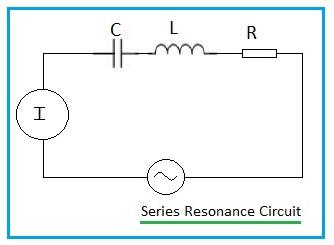
Series Resonance
If the capacitor and inductor are connected in series, as shown in Figure 1, the condition is known as series resonance, and the circuit is called a series resonant circuit.
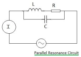
Parallel Resonance
Conversely, if the components are connected in parallel, as depicted in Figure 2, we have parallel resonance, and the circuit is a parallel resonant circuit.
The Core Concept of Resonance
In simpler terms, resonance in AC circuits occurs when the inductive reactance () is exactly equal to the capacitive reactance (). Mathematically:
This translates to:
The impedance (Z) of the circuit can be calculated as:
Resonance Frequency
The resonance frequency () is the frequency at which resonance occurs in an L-C circuit. It is given by the formula:
Where:
- = resonant frequency (Hertz)
- L = Inductance (Henrys)
- C = Capacitance (Farads)
At this frequency, the reactances cancel each other out, leading to a purely resistive impedance.
Series Resonance Circuit in Detail
A series L-C circuit where the capacitive and inductive reactances are equal is a series resonant circuit. It is sometimes referred to as an acceptor circuit.
At the resonant frequency, the impedance of the circuit is at its minimum, resulting in maximum current flow.
Characteristics of Series Resonance Circuits
- Minimum impedance
- Maximum circuit current
- , indicating current and voltage are in phase.
- Circuit current is proportional to circuit resistance:
Uses of Series Resonance Circuits
- Frequency selection in radio and TV tuners
- Band-pass filter circuits
Circuit Q or Q Factor
The Q factor (Quality factor) represents the ratio of inductive reactance to resistance in a circuit. It’s also known as the magnification factor.
Where:
- Q = circuit-Q (unitless)
- = inductive reactance (Ohms)
- R = circuit resistance (Ohms)
Selectivity is directly proportional to the Q factor. The bandwidth of the resonance curve is given by:
Where:
- = Upper frequency of bandwidth (Hertz)
- = Lower frequency of bandwidth (Hertz)
- R = circuit resistance (Ohms)
- L = Inductance (Henrys)
Parallel Resonance Circuit in Detail
A parallel L-C circuit with equal capacitive and inductive reactances is a parallel resonant circuit, also known as a rejector circuit.
At resonance, the circuit impedance is at its maximum, leading to a high voltage across the load resistor.
Characteristics of Parallel Resonance Circuits
- Maximum impedance
- Minimum circuit current
- , voltage and current are in phase
- Circuit current depends on impedance: or
Uses of Parallel Resonance Circuits
- Band-stop filters
- Tank circuits in oscillators
- Plate loads in IF and RF amplifiers
- I.F. trap in aerial circuits of radio and TV receivers
Difference between Series and Parallel Resonance
Here’s a table summarizing the key differences:
| Parameters | Series Resonance Circuit | Parallel Resonance Circuit |
|---|---|---|
| Impedance at resonance | Minimum | Maximum |
| Current at resonance | Maximum | Minimum |
| Voltage at resonance | Minimum | Maximum |
| Effective impedance | R | L/CR |
| Resonant frequency | ||
| Magnifies | Voltage | Current |
| Bandwidth | Narrow | Wide |
| Quality Factor | High | Low |
| Alternative Name | Acceptor circuit | Rejector circuit |
Conclusion : The selection between series and parallel resonance depends on the specific application requirements. Both involve the exchange of energy between the inductor and capacitor, resulting in a strong response at the resonant frequency. Series resonance is typically used in RF applications, filters, and tuning circuits, while parallel resonance finds use in audio applications, notch filters, and impedance matching.
Advertisement


