Resistor Basics: Types, Color Codes, Series and Parallel Circuits
Advertisement
The discrete electronic resistor is used to control the flow of current by inserting resistance in the path. It’s a fundamental component used in countless electronic circuits for several key reasons:
- To obtain desired voltages (power) at various points in a circuit.
- To create variable voltage from a fixed voltage source using a variable resistor.
- To generate changing voltage by utilizing a changing current across a resistance, common in voltage amplifiers.
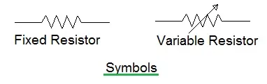
Figure-1 depicts fixed resistor and variable resistor symbols.
When you’re purchasing or selecting a resistor, several specifications are important: tolerance, power rating, and stability (against temperature and physical conditions). Resistance is measured in Ohms.
Fixed resistors, as the name suggests, don’t change their resistance value. They come in various types based on their design and the materials used, such as carbon composition, carbon film, metal oxide, and wire wound. Metal oxide resistors offer the highest stability over long periods. Wire wound resistors are often used in multimeter designs due to their low tolerance (good accuracy) and high stability.
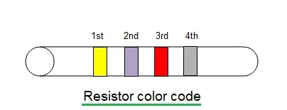
The resistor value is often indicated using a color code. The first few bands provide the resistance value, and the last band typically indicates the tolerance. Usually, the first two bands give the first two digits of the resistance, and the third band indicates the number of zeros to add.
Tolerance is specified by the color of the fourth band. Here’s a breakdown:
Value Codes
| Number | Band Color |
|---|---|
| 0 | Black |
| 1 | Brown |
| 2 | Red |
| 3 | Orange |
| 4 | Yellow |
| 5 | Green |
| 6 | Blue |
| 7 | Violet |
| 8 | Grey |
| 9 | White |
For example, if a resistor has color bands of yellow (4), violet (7), red (two zeros), and silver, its value would be 4700 Ohms with a tolerance of +/-10%.
Tolerance Codes
| Percentage | Band Color |
|---|---|
| +/-5 | Gold |
| +/-10 | Silver |
| +/-20 | No fourth band |
Resistors in Series
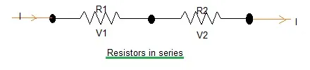
When resistors are connected in series (one after the other), a few principles apply:
- The current flow (I) is the same through all of them.
- The total voltage is the sum of the voltage drops across each resistor: , which can be expressed as .
- The total resistance is the sum of the individual resistances: .
Resistors in Parallel
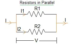
When resistors are connected in parallel (side-by-side), the following is true:
- The voltage across each resistor is the same.
- The total current is the sum of the currents through each resistor: , or .
- The total resistance (R) is calculated as: .
Depending on the application, resistors in series and parallel configurations are used in electronic circuit design to achieve desired resistance values and current/voltage characteristics.
Resistor Manufacturers
There are numerous resistor manufacturers worldwide, including Mouser Electronics, Vishay, Riedon, Murata, Precision Resistor, Ohmite, InnovativePP, and SRT-restech, among others.
Vishay resistors and capacitors are often considered very accurate and are used in a wide variety of applications. Users can choose resistors based on various technologies (thick film, thin film, carbon film, metal oxide film, wirewound) and mounting styles (leaded and surface mount).