
TE11 vs TM11 Mode: Understanding the Difference in Waveguides
Advertisement
This page explains the difference between the TE11 mode and the TM11 mode. Let’s dive into the details!
Cutoff wavelength in a rectangular waveguide is defined by the following formula:
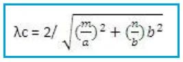
Where:
- ‘m’ = number of half-waves along the broad side dimension
- ‘N’ = number of half-waves along the shorter side
TE11 mode
- In a TE11 mode, there exists one half wave of the electric (E) field in both the broader and shorter dimensions.
- The electric field has no component in the direction of wave propagation (i.e. longitudinal direction).
- TE11 is dominant mode in circular waveguide. It has the lowest cutoff frequency and is the most efficient for signal transmission.
- Applications: Commonly used in microwave and RF systems due to its efficient propagation characteristics.
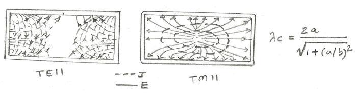
TM11 mode
- Conversely, in a TM11 mode, there exists one half wave of the magnetic (H) field in both the broader and shorter dimensions.
- The magnetic field has no component in the direction of wave propagation.
- TM11 has higher cutoff frequency compared to TE11, making it less efficient for signal transmission.
- Applications: Utilized in certain resonant cavity designs
Advertisement


