Cross Modulation vs. Intermodulation: Key Differences
Advertisement
This article explains the difference between cross modulation and intermodulation. Both are crucial concepts in RF (Radio Frequency) engineering, as they can lead to receiver malfunction due to overload and the generation of unwanted harmonics and other intermodulation products.
What is Cross Modulation?

Cross modulation is a type of intermodulation distortion that occurs when multiple carriers are present within the same bandwidth. This often happens when a strong, nearby, unwanted AM (Amplitude Modulation) signal interferes with a weaker, desired AM signal. The effect is noticeable on the weaker input signal, potentially overloading the receiver.
Examples:
- Cable TV: Cross modulation can be observed in cable TV systems, where a single amplifier is used to amplify multiple channels simultaneously.
- OFDM Systems: OFDM (Orthogonal Frequency Division Multiplexing) based systems, like WiMAX or WLAN, use multiple carriers within the bandwidth of a single amplifier, making them susceptible to cross modulation.
Measurement:
To measure cross modulation, you can turn on all tones or carriers except one and measure the power at the frequency of the deactivated carrier.

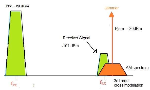
Fig-2 illustrates the frequency spectrum of various signals. The “jammer” signal is located just outside the edge of the channel filters. Consequently, a significant portion of the cross-modulation signal falls within the filter’s passband. If the LNA’s (Low-Noise Amplifier) IP3 (Third-Order Intercept Point) is not high enough, the cross modulation power within the filter’s passband may exceed the total thermal noise power.
The cross-modulation power can be expressed by the following equation:
P crossmod = 6 + 2\*( P txin - P IIP3 ) + Pj
Where all units are in dBm.
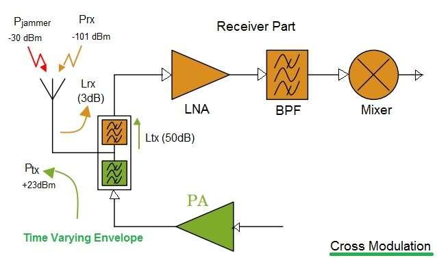
For smaller jammer signals, cross modulation can manifest as a time-varying gain compression of the LNA, especially due to transmitter leakage signals employing non-constant envelope modulation. The cross-modulation noise power represents the total power within the AM spectrum around the single-tone jammer. Smaller cross-modulation power values correlate with larger IP3 values for the LNA.
Cross Modulation Testing
Cross modulation testing is typically performed using two-tone tests. A frequency spacing is maintained between the desired and undesired signals. The desired signal is usually set to a power level of -53 dBm. The undesired signal is amplitude-modulated with a 30% level and placed 20 kHz away from the desired signal. The power of the undesired AM modulated signal is increased until the unwanted AM output is 20 dB below the desired signal power.
A cross-modulation specification of >=100dB is generally considered to provide good system performance. Receivers with higher TOI (Third-Order Intercept) points also tend to exhibit better cross-modulation system performance.
Intermodulation
Intermodulation distortion becomes relevant in devices that handle multiple frequencies. It includes second-order and higher-order intermodulation distortions. You can refer to articles explaining second-order vs. third-order intercept points, which describe intermodulation products, the TOI point, and the IP2 (Second-Order Intercept Point).
Advertisement
 RF
RF


