
USB Protocol Stack: V2.0 and V3.2
Advertisement
This page describes the USB Protocol Stack and the functions of each layer. It mentions the USB Protocol Stack as per USB V2.0 and USB Protocol Stack as per USB V3.2.
Introduction
The USB stands for Universal Serial Bus. It is an interface similar to RS232 and RS485 but supports higher data rates at various distances. USB supports peer-to-peer communication. In this type of interface, communication takes place between a host and a peripheral, and not between two hosts (or peripherals).
The USB standard defines specifications for cables, connectors, and protocols. It mentions requirements for connection, communication, and power supply (PS) between PCs and peripheral devices. The USB device can be directly connected to a Host or through a Hub.
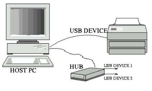
There are various versions of USB which include v1.x, v2.x and V3.x. Each of these versions support different data rates viz. 60 Mbps, 625 Mbps and 1.25-2.5 Gbps respectively. USB 2.0 is known as high speed, USB 3.0 is known as superspeed and USB 3.2 is known as superspeedplus. USB standards support cables with length upto 5 meters. Beyond this, USB hubs are required to expand connectivity.
USB Protocol Stack as per V2.0
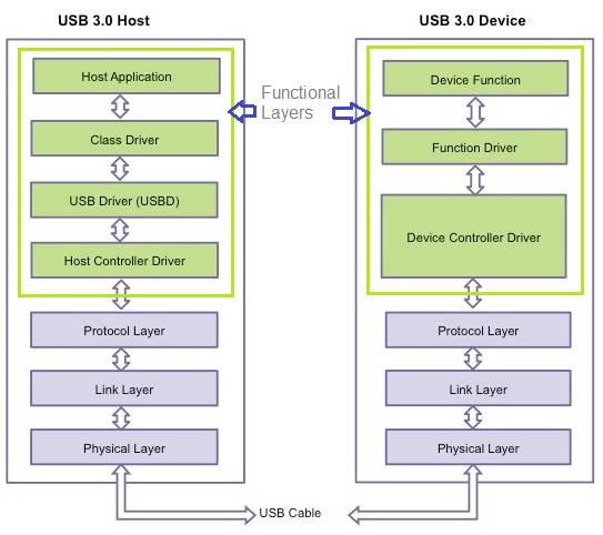
Figure-1 depicts the USB protocol stack as per V2.0. The protocol stack mentions various layers through which data flows between host and device. The following section mentions the roles or functions of USB protocol layers.
Functional Layer
This layer generates requests which are converted into transactions containing different packets. This layer manages end-to-end data flow between host and device. The figure mentions sub-layers of functional layers of both host and device.
Protocol Layer
Packets originate at the transmit part of the protocol layer and terminate at the receive part of the protocol layer. It has various functions which include the following:
- Ensure end-to-end reliability of packets.
- Ensure effective management of power.
- Ensure effective use of Bandwidth.
Link Layer
This layer manages port-to-port flow of data between USB host and device. Here link is logical and physical connection between the ports viz. upstream and downstream facing ports. Link layer commands are used between two linked ports to communicate information between upstream and downstream ports. Hence these commands ensure link level data integrity, flow control and power management. This layer handles packet acknowledgement and takes care of error recovery. The Link Layer also handles Header Packet Framing. Its functions are similar to the MAC layer of the OSI model.
Physical Layer
This layer offers actual physical connection between two ports. The connection uses two differential data pairs viz. one transmit path and one receive path. The transmit part of the physical layer performs data scrambling, 8b10b encoding, and serialization functions. The receive part of the physical Layer performs de-serialization, 8b10b decoding, data descrambling, and receiver clock and data recovery.
USB Protocol Stack as per V3.2
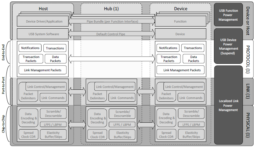
Figure-2 depicts the USB protocol stack layers at the host and device as defined in the USB3.2 standard.
Advertisement


