 RF
RFRF vs PHY: Understanding the Key Differences
Advertisement
The comparison of RF vs PHY often confuses beginners in communication systems. RF (Radio Frequency) refers to the electromagnetic signals used for wireless transmission, while PHY (Physical Layer) pertains to the OSI model layer responsible for the physical encoding and decoding of data. This guide clarifies the difference between RF and PHY layer, emphasizing their distinct yet interconnected roles in networking based on their functions, interfaces, applications, and other parameters.
Introduction
The OSI model has been developed to establish communication between open systems. The OSI model has seven layers. Each of these layers has well-defined functions and they support the layers above and below it. Both RF (Radio Frequency) and PHY (Physical) layers are mapped to layer-1 of the OSI stack.
RF layer is present when the medium is wireless. PHY is known as the baseband layer, whereas RF is known as the wireless layer, based on operations performed.
The figure-1 depicts OSI stack with the position of PHY and RF layers one above the other.
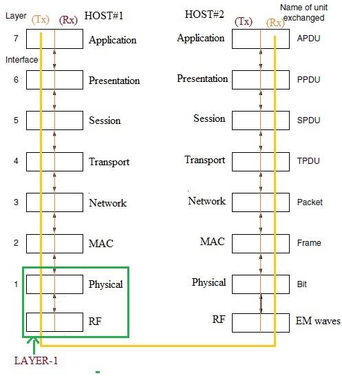
Figure-1: RF and PHY in OSI stack
Layer-1 deals with the transmission of information in a form suitable for wired/wireless medium such that they can be retrieved at the receiver end. It takes care of error recovery at the receiver caused by the channel (wired medium or wireless medium).
The figure-1 depicts the OSI stack of two hosts. The figure shows peer-to-peer communication between two hosts and the unit of data exchanged at different layers. All the layers consist of transmitter (Tx) and receiver (Rx) parts inside both the hosts. RF layer exists only in wireless nodes or hosts.
Example #1: The communication between AP (Access Point or router) and Station (STA or client) follows the same communication mechanism in WLAN (Wireless LAN).
Example #2: Similarly, communication between a Base Station and Mobile subscriber follows the same protocol mechanism as per standard specifications.
What is RF Layer
RF is the short form of Radio Frequency, which is used for the transmission of EM waves into the air using an antenna. RF signals are characterized by their frequency (i.e., number of cycles per second measured as hertz). One hertz equals 1 cycle per second.
Where:
-
c is the speed of light, equals 3 x 10⁸ m/sec
-
λ is the signal wavelength (i.e., distance between 2 consecutive peaks)
-
Lower is the frequency, longer is the wavelength. Hence lower frequencies travel longer distances compared to higher frequencies. Different RF frequencies are used as per standards such as WLAN, Zigbee, GSM, LoRa, Sigfox, 4G LTE, 5G, etc.
The figure-2 below depicts RF and Baseband (i.e., PHY) parts of a wireless node or device.
RF Frequencies are measured in units of Hz, KHz, MHz, GHz, THz etc.
1 Hz of frequency equals 1 second of period, 1 KHz equals 1 ms, and so on.
Following parameters are very useful and used often with the RF signal.
- Frequency: Number of cycles per second, measured in Hertz as explained above.
- Wavelength: Distance between 2 consecutive peaks, measured in meters/centimeters as explained above.
- Power: Strength of the RF signal, measured in dB, dBm, dBW etc. Higher transmit power of the RF signal helps it to travel more distance from its originating source. RF passive devices such as attenuators, RF Mixers, Isolators cause the RF signal to get attenuated. RF amplifiers cause the RF signal to get amplified. These gains and losses are measured in the unit of decibel.
- Bandwidth: Width of RF spectrum, measured in Hz/KHz/MHz/GHz. It helps to know how much information an RF signal can carry.
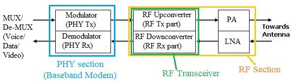
Figure-2: RF modules
The baseband data such as voice or data or video are passed through the modulator and given as input to the RF transmitter. After necessary frequency translation by RF upconverter, the RF upconverted signal is amplified by PA (Power Amplifier) before transmission into the air by RF antenna.
At the receiver reverse operations take place such as LNA (Low Noise Amplification), RF down conversion, demodulation etc. to retrieve baseband information. The upconversion and down conversion is carried out using appropriate RF mixers, suitable LOs or RF synthesizers, Band Pass Filters (BPFs), amplifier MMICs, attenuator pads etc.
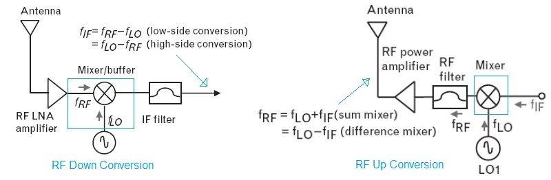
Figure-3: RF Up conversion and Down conversion process
Following are the functions of the RF layer.
- At the transmitter, it modulates baseband data using an RF carrier as per the system using an RF Up converter. This modulated RF signal is amplified using PA (Power Amplifier) before transmission into the air (by Antenna) or other medium as per system design.
- At the receiver, the received RF modulated signal is amplified using LNA (Low Noise Amplifier) first. This amplified signal is down converted using an RF down converter and fed to the baseband receiver.
What is PHY Layer
PHY stands for Physical, the keyword often used for the Physical layer of OSI stack layer-1. It interfaces with MAC/upper layers at one end and with wired or wireless medium (i.e., RF) at the other end. The physical medium can be copper wire, twisted pair, fiber optic cable, or space/vacuum.
The amplitude, frequency, and phase of the RF signal are used to map or demap PHY data during transmission and reception respectively.
Following are the functions of the PHY layer. It provides services to layers above and below itself i.e., Network/upper layers and wired medium or wireless (i.e., RF) medium.
- It makes higher layer data suitable for transmission over the desired medium. It adds a header and trailer as per the transmission medium used.
- It introduces redundant data as per the FEC technique (CC/CTC) at the transmitter to provide error correction at the receiver.
- It converts bits to symbols as per the modulation technique used. This increases the bandwidth efficiency of the system.
- For example, In QPSK, 2 bits are mapped to 1 symbol
- In 16QAM, 4 bits are mapped to 1 symbol, and so on.
- It uses modules such as scramblers and interleavers to meet specific requirements of the wireless channel.
- The PHY receiver takes care of time synchronization, frequency synchronization, and channel equalization.
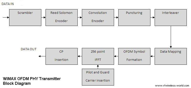
Figure-4: PHY (i.e., Baseband) Transmitter Modules (as per IEEE 802.16-2004 WiMAX standard)
The figure-4 depicts typical PHY layer modules. The MAC layer output (i.e., “Data In”) is given as input to PHY Tx (Transmitter) chain. The “Data Out” refers to PHY Tx output which is fed to RF Transmitter (i.e., Upconverter) through DAC.
Different PHY layers will have different FEC configurations and modulation formats.
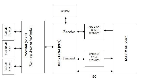
Figure-5: Interfacing RF and PHY
As shown in the figure-5, the PHY layer is implemented on FPGA/Processor, and upper layers such as MAC/IP are implemented on Processor. Memory is used between PHY and MAC for data exchange. RF and PHY layers are interfaced using DAC in the transmit chain and using ADC in the receive chain as shown.
Difference between RF and PHY
The following table mentions the comparison between RF and PHY layers with respect to various parameters.
| Parameters | RF Layer | PHY Layer |
|---|---|---|
| Full Name | Radio Frequency layer, It is also known by RF Transceiver. | Physical layer, It is also known by modem (Modulator Demodulator) or baseband layer. |
| Function | Converts information (in analog or digital form) into Electro-Magnetic (EM) waves suitably to be transmitted over the air medium and vice versa. Different frequency channels are used for transmission and reception of EM waves as per standards such as WLAN, Bluetooth, Zigbee, GSM, 4G LTE, 5G etc. RF transmitter converts bits to EM waves where as RF Receiver converts EM waves to bits. | Converts MAC/Upper layer data bits in the suitable form to be transmitted over wired/wireless medium. It performs a number of operations on MAC data such as randomization, encoding, interleaving, data mapping and so on at the PHY transmitter. It performs reverse operations such as data demapping, de-interleaving, decoding, de-randomization at the PHY receiver. |
| Interfaces | RF layer interfaces with PHY layer at one end through ADC/DAC and with RF antenna at the other end as shown. | PHY layer interfaces with RF layer at one end through ADC/DAC and with MAC layer at the other end as shown. |
| Frequency | Radio Frequency uses 1 to 3 GHz in the EM spectrum. Microwave uses 3 to 30 GHz and mmwave uses 30 to 300 GHz. | PHY or baseband data uses very low frequencies, which are modulated using higher RF carrier frequencies before transmission as per standards/countrywide regulatory allocations. Audio signal occupies 20 Hz to 20 KHz. The frequency of a digital signal ranges from 0 Hz to sampling frequency (fs) of ADC (Analog to Digital Converter). |
| Medium of propagation | EM waves propagate in vacuum, space, solid state medias such as circuit board metals or coaxial cables, waveguides etc. | PHY or baseband data signals propagate through wired mediums such as PCB circuit traces, ethernet or using RS232/RS485 etc. |
| Modules | It consists of basic modules such as RF Transceiver (RF Transmitter and Receiver), PA (Power Amplifier) and LNA (Low Noise Amplifier). | It consists of basic modules such as scrambler or randomizer, interleaver, FEC encoder (Convolutional encoder, CTC encoder), Interleaver, data mapper, IFFT etc. in the PHY transmitter and reverse modules in the PHY receiver. It addition PHY receiver consists of time, frequency and channel equalization modules to compensate for time offset, frequency offset and channel impairments. |
| Measurements | RF Frequency and Power are very basic measurements of the RF signal. The advanced RF measurements include spurious, harmonics, phase noise, frequency stability, 1dB/TOI measurements etc. | Time period, Pulse amplitude and eye diagram are very basic measurements of the PHY layer signal. The advanced PHY measurements include I/Q diagram, EVM, spectral flatness, PAPR etc. |
| Examples | MAX2830 from Maxim (Now Part of Analog Devices) which supports 2.4 GHz to 2.5 GHz is an RF Transceiver suitable for WLAN (802.11g/b) standard. This SoC houses PA, LNA, Rx/Tx antenna switch, LO, PLL and so on. RF Transceiver SoCs are available for different standards (WLAN, WiMAX, Zigbee, Bluetooth, LoRa, Sigfox, GSM, 4G LTE, 5G etc.) from various vendors. | WF200 from Silicon Labs is a WiFi Transceiver IC. It houses 802.11b/g/n PHY layer, MAC layer and RF layer. |
Conclusion
The difference between the RF and PHY layer lies in their focus: RF deals with wireless signal transmission, while the PHY layer ensures proper data encoding and decoding. Together, they create a robust framework for modern communication networks.
Advertisement


