 RF
RFRF Circulator: Working Principle and Applications
Advertisement
This page explains how an RF circulator works. It includes its terminal diagram and operational principles.
Definition: A non-reciprocal ferrite device with 3 or more ports, where an input from port-N leads to an output at port N+1, is known as a circulator. When this device operates at radio or microwave frequencies, it’s called an RF Circulator. A 3-port circulator is often referred to as a Y-Junction Circulator.
RF circulators are available in both waveguide and stripline forms. Based on the direction of signal travel, there are two main types: clockwise and anti-clockwise circulators.
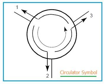
Figure 1 depicts an anti-clockwise circulator. As shown, the signal flows from port 1 to port 2, from port 2 to port 3, and from port 3 to port 1.
This means a signal input at port 1 will result in a signal output from port 2, with ideally no signal output from port 3, and so on. This behavior is due to the low insertion loss (typically a few tenths of a dB) from port 1 to port 2. The loss from port 1 to port 3 is known as isolation, which is typically quite high (around 20 to 25 dB).
An RF circulator becomes an Isolator when one of its ports is terminated with a matched impedance. For example, if port 3 in Figure 1 is loaded, then power at port 1 is available at port 2. All reflections from port 2 will be directed to the load at port 3, preventing any reflections from returning to port 1.
Circulators can be utilized as diplexers and triplexers by incorporating appropriate filters at the respective ports. Because circulators contain magnets, they should be kept away from ferrous metals. Close proximity to metals can alter the frequency response of the circulator.
How RF Circulator Works | RF Circulator Working
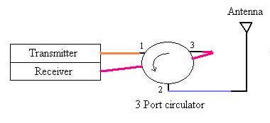
Figure 2 illustrates the use of an RF circulator to share a single antenna between transmitter and receiver units. The circulator used here is an anti-clockwise type.
- Let’s consider the arrangement shown in Figure 2, where the transmitter is connected to port 1, the receiver to port 3, and the antenna to port 2.
- In this configuration, due to the anti-clockwise nature of the circulator, any data to be transmitted will travel from port 1 to port 2 and be transmitted from the antenna.
- Conversely, any data received by the antenna connected to port 2 is coupled to port 3, allowing the receiver to decode the signal.
Advertisement


