 RF
RFGPS Sensor Function and Working Explained
Advertisement
This page describes GPS Sensor basics, including the GPS sensor function and GPS sensor working, along with a GPS system diagram.
What is a GPS Sensor?
As we know, GPS stands for Global Positioning System. The system contains satellites and ground-based control installations.
A GPS sensor consists of a surface-mount chip that processes signals from GPS satellites using a small, rectangular antenna, often mounted on the top of the GPS chip.
- A GPS module is usually a small board on which a GPS sensor is mounted, along with additional components.
- A GPS receiver is a device that includes a data display and other components, such as memory for data storage, in addition to the GPS module.
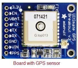
Figure 1 depicts a breakout board along with a GPS sensor offered by Adafruit industries.
The GPS system consists of three segments:
- Space segment
- Control segment
- User segment
The space segment contains about 31 satellites as of August 2018, located in orbit about 12,500 miles above the Earth. Hence, each of these satellites circles twice in 24 hours.
The control segment contains command, control, and monitoring stations.
The user segment consists of receiving devices (e.g., both government and private).
GPS Sensor Working Operation
Let’s understand how a GPS sensor works.
-
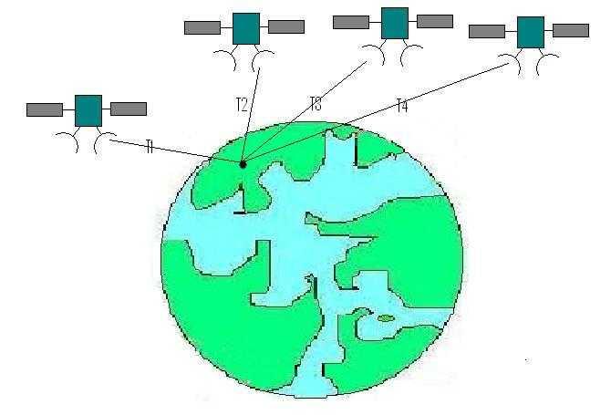
As shown in Figure 2, about four satellites are needed to determine a position on Earth in 3-dimensional space.
-
Each of these satellites carries multiple atomic clocks, which maintain precise time, and a pseudo-random number generator in the form of a linear feedback shift register.
-
A GPS receiver can distinguish signals from at least four satellites by comparing their received pseudo-random bit sequences and can calculate the receiver’s distance to each of these satellites by comparing the arrival times of the satellite signals.
- Distance = transit time (sec) x speed of light (meter/sec)
-
GPS satellites transmit on several frequencies simultaneously. One such frequency, known as L1 (1575.42 MHz), is used for civilian applications, whereas the other frequency, L2 (1227.6 MHz), is used for military applications.
Refer to GPS and GNSS frequency bands for more information on GPS and GNSS frequencies.
- A GPS module housing a GPS sensor requires a DC power supply. It starts outputting data as soon as it identifies the satellites within its range. The data follows a plain ASCII protocol known as the NMEA protocol. The transmission rate is either 4800 bps or 9600 bps and uses {8 bits, no parity, 1 stop bit} for decoding. The data blocks are known as sentences, which are about 80 characters in length.
Refer to GPS Sentences for more information.
These GPS sentences contain latitude, longitude, altitude, and data recording time. These sentences are decoded by connecting a microcontroller with the GPS module and writing a small program. Refer to the application note on interfacing a GPS sensor with an Arduino Uno board, including a pin-to-pin block diagram and source code.
Advertisement


