 RF
RFElectrical to Optical and Optical to Electrical Transducers
Advertisement
This page compares electrical to optical transducers and optical to electrical transducers, outlining the differences between the various types.
Introduction
Fiber optic systems offer numerous advantages, including large bandwidth for high-speed data transmission, immunity to electromagnetic interference, lightweight construction, and low signal loss. These benefits make them ideal for carrying large bandwidth data across undersea cables, connecting exchanges, and linking buildings near microwave antennas.
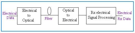
To transmit electrical data over fiber optic cables, it must first be converted into optical form. This conversion is accomplished using an electrical to optical transducer at the transmitting end. Conversely, at the receiving end, the optical data must be converted back to its original electrical format using an optical to electrical transducer.
Electrical to Optical Transducer
Electrical to optical transducers are used at the transmitter end of fiber optic systems to convert electrical signals into optical signals. Common devices include:
- LED (Light Emitting Diode): LEDs are inexpensive and reliable, typically used for lower bandwidth applications.
- LD (Laser Diode): Laser diodes offer a narrow spectrum and are suitable for higher bandwidth applications.
LED Features
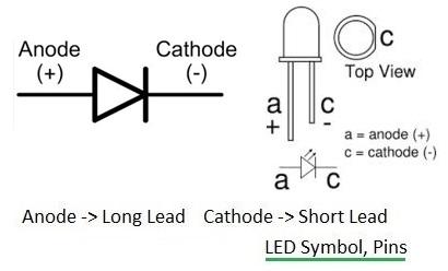
- Made from gallium arsenide phosphide.
- Converts electrical signals to optical signals in the infrared wavelength (approximately 850 nm). PCM signals are converted to infrared pulses.
- Used in low data rate transmission systems with speeds up to 30 Mbps.
- LEDs have anode and cathode terminals.
Laser Diode Features
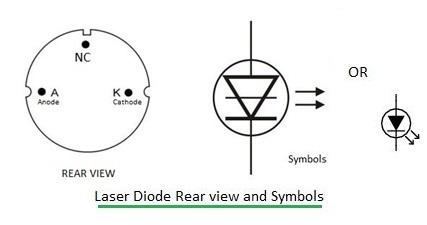
- Made of gallium arsenide phosphide.
- Power output is approximately 10mWatt.
- Faster ON/OFF switching speed compared to LEDs.
- Narrower spectral width (10-5 to 5 nm).
- High modulation bandwidth, ranging from tens of MHz to tens of GHz.
Optical to Electrical Transducer
Optical to electrical transducers are used at the receiver end of fiber optic systems to convert optical signals back into electrical signals. Common devices include:
- PIN Diode: Performs well at low bandwidths.
- Avalanche Diode: Operates at higher data rates.
Different materials are used to produce light at different wavelengths, including silicon (190 to 1100 nm), germanium (400 to 1700 nm), InGaAs (800 to 2600 nm), and Lead Sulfide (<1000 to 3500 nm).
PIN Diode Features
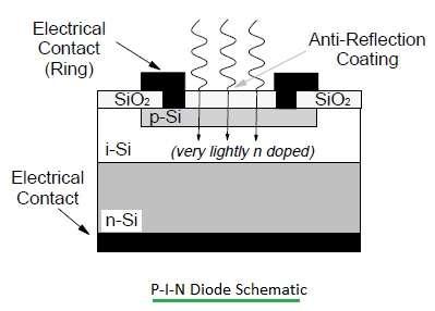
- Absorbs optical light when photons of any wavelength fall on it and converts it to electrical energy.
- Has an intrinsic (I) layer between the P and N materials, with a small amount of dopant and a wide depletion region.
- Requires a reverse bias voltage of 3 volts.
Avalanche Diode Features
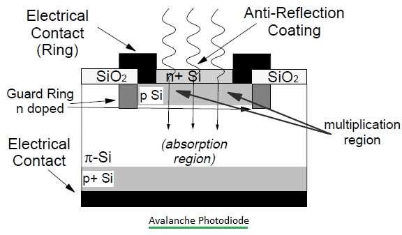
- Amplifies the signal in addition to optical detection.
- Consists of n+, p, π, and p+ regions in its structure.
- Absorbs photons in the π region, generating electron-hole pairs, thus converting the optical signal to an electrical signal.
- Essentially a PIN diode with a very high reverse bias voltage.
- Requires a reverse bias voltage of 50 volts.
Advertisement


