difference between CB,CE,CC transistor configurations
Advertisement
This page compares the CB, CE, and CC transistor configurations, highlighting the differences between these modes. These modes are used in various transistor-based applications depending on their characteristics, as detailed below.
As we know, a transistor is the solid-state equivalent of a triode vacuum tube. It’s a solid-state, current gain device with three terminals:
- Collector
- Base
- Emitter
Transistors are made using both p-type and n-type materials, which is why they’re available in PNP and NPN configurations. This type of transistor is referred to as a bipolar transistor.
There are three basic configurations for transistors:
- Common Base (CB)
- Common Emitter (CE)
- Common Collector (CC)
These are used in electronic circuits for different purposes. The important characteristics of these different modes or configurations are described below. These characteristics dictate their use in different applications.
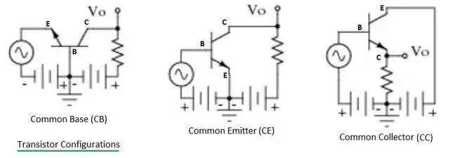
Figure 1 depicts all three transistor configurations used in various electronic circuit applications.
Transistor CB (Common Base) Configuration
This is a transistor circuit where the base is common to both the input and output circuits.
Characteristics:
- Low input impedance (on the order of 50 to 500 Ohms).
- High output impedance (on the order of 1 to 10 Mega Ohms).
- Current gain (alpha) is less than unity.
Transistor CE (Common Emitter) Configuration
This is a transistor circuit where the emitter is common to both the input and output circuits.
Characteristics (applications):
- High input impedance (on the order of 500 to 5000 Ohms).
- Low output impedance (on the order of 50 to 500 Kilo Ohms).
- Current gain (Beta) is around 98.
- Power gain is up to 37 dB.
- The output is 180 degrees out of phase with the input.
Transistor CC (Common Collector) Configuration
This is a transistor circuit where the collector is common to both the input and output circuits. It’s also known as an emitter follower.
Characteristics:
- High input impedance (on the order of about 150 to 600 Kilo Ohms).
- Low output impedance (on the order of about 100 to 1000 Ohms).
- Current gain (Beta) is about 99.
- Voltage and power gain is equal to or less than one.
Comparison between CB, CE and CC Transistor Configurations
| Parameter | Common Base | Common Emitter | Common Collector |
|---|---|---|---|
| Input terminal | Emitter | Base | Emitter |
| Output terminal | Collector | Collector | Collector |
| Voltage Gain | Low | Moderate | Slightly Less than 1 (Unity gain) |
| Current Gain | Medium | High | Low current gain (current buffering) |
| Power Gain | Low to Moderate | Moderate to High | Very close to 1 (unity) |
| Phase inversion | No (0 or 360 degrees) | Yes (180 degrees) | No (0 or 360 degrees) |
| Input Impedance | Low (50 Ohm) | Moderate (1 KOhm) | High (300 KOhm) |
| Output Impedance | High (1 M Ohm) | Moderate (50 K) | Low (300 Ohm) |
| Applications | High-frequency amplifiers, RF Circuits | General purpose amplifiers, power amplifiers | Voltage buffering, impedance matching |
In summary, the choice of transistor configuration (CB, CE, or CC) depends on the specific requirements of the circuit and the desired characteristics, such as voltage gain, current gain, input/output impedance, and phase relationships. CE is the most commonly used configuration for amplification, while CC is often used for impedance matching and signal buffering. CB is primarily employed in high-frequency applications.