BJT vs FET: Understanding the Key Differences
Advertisement
BJT (Bipolar Junction Transistor) and JFET (Junction Field-Effect Transistor) or FET are two types of transistors used in electronic circuits.
Both are semiconductor devices used for signal amplification and switching purposes. They do share some similarities but differ in terms of their symbols, structures, characteristics and applications.
Understanding the advantages of each transistor type helps engineers and designers select the most appropriate component for their particular needs.

BJT Transistor
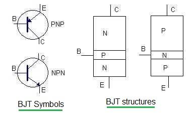
The term BJT stands for Bipolar Junction Transistor. BJT is the current controlled device. As shown in the figure, there are PNP and NPN type of BJT transistors. The symbols of these transistors are also depicted in the figure.
There are three terminals in a BJT device viz. emitter,base and collector. The symbol for a PNP transistor has an arrow on the emitter terminal points away from the base terminal. The direction of the arrow in PNP transistor indicates the direction of conventional current flow from the emitter to the base.
The symbol for a NPN transistor has an arrow on the emitter terminal points toward the base terminal. The direction of the arrow in NPN transistor indicates the direction of conventional current flow, in this case, from the base to the emitter.
- Trans-conductance gm = ε vs W/d
- Cutoff frequency fT = gm/(2pCgs)
Following are useful characteristics of BJT:
- Its input impedance is low and output impedance is high.
- Noisy device due to presence of minority carriers.
- It is bipolar device as current flows due to both majority and minority carriers.
- Thermal stability is lesser due to leakage current or reverse saturation current.
- Doping in emitter is highest and in base it is lowest.
- Area of collector is highest and that is base is lowest.
BJT applications or uses
Following are the uses or applications of BJT.
- Amplifications of signals (Commonly used in audio and RF amplifiers).
- Switching applications
- Digital logic circuits (less common than FETs)
- Voltage regulators
BJT advantages
Following are the benefits or advantages of BJT transistor.
- High gain at low frequencies
- Good linearity
- Simple to use in amplification circuits
BJT disadvantages
Following are the drawbacks or disadvantages of BJT transistor.
- Higher power consumption
- Relatively slower switching speeds compared to FETs
- Temperature sensitive
FET Transistor
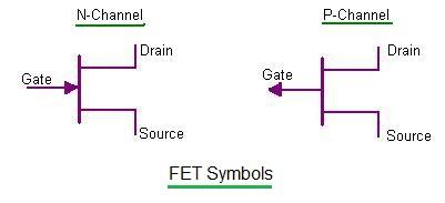
The term FET stands for Field Effect Transistor. FET is the voltage controlled device. Figure depicts FET symbols for P channel and N channel type.There are three terminals in a FET device viz. source, drain and gate. The source is the terminal through which the carriers enter the channel. The drain is the terminal through which carriers leave the channel.The gate is the terminal that modulates the channel conductivity by application of voltage to this terminal.

N-channel and P-channel FETs have specific symbols as shown with three terminals (source, gate, drain). In the N-channel FET, arrow in the symbol points in the direction of electron flow from the source to the drain. In the P-channel FET, arrow in the symbol points in the opposite direction compared to the N-channel FET, indicating the flow of holes from source to drain.

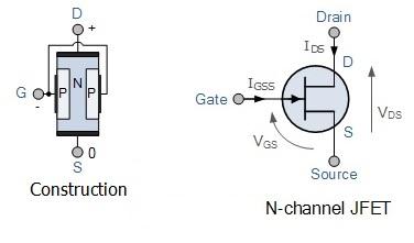
N-channel FETs are typically made from an N-type semiconductor material. They operate by controlling the flow of electrons (negative charge carriers) from the source (S) to the drain (D) terminal in response to a voltage applied at the gate (G) terminal.

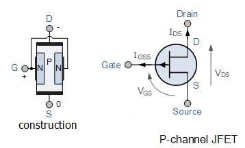
P-channel FETs are typically made from a P-type semiconductor material. They operate by controlling the flow of holes (positive charge carriers) from the source (S) to the drain (D) terminal in response to a voltage applied at the gate (G) terminal.
FET is referred as unipolar transistor. In FET input voltage controls the output current, here input current is usually negligible. This is the great merit of FET when input can not supply much current.
- Trans-conductance- gm = q I e /kBT
- Cutoff frequency- fT = 2D n /WB 2
Following are useful characteristics of FET which mentions difference between BJT and FET features.
- It is a high input impedance device about 100 MOhm and above.
- FET has no offset voltage when used as switch unlike BJT.
- FET is relatively immune to radiation but BJT is very sensitive.
- It is a majority carrier device.
- FET is less noisy compare to BJT. It is more suitable for input stages of low level amplifiers.
- FET provides greater thermal stability compare to BJT.
- FET is a unipolar device.
FET applications or uses
Following are the uses or applications of FET.
- High frequency amplifiers
- Low noise amplifiers (Common in RF applications)
- Analog switches
- CMOS logic gates (NMOS and PMOS)
JFET transistor advantages
Following are the advantages of JFET transistor.
- High input impedance
- Low power consumption
- Faster switching speeds
- Less temperature sensitive
JFET disadvantages
Following are the drawbacks or disadvantages of FET transistor.
- Lower gain at low frequencies compared to BJTs
- FET suffers from greater susceptibility to static electricity damage and hence requires careful handling.
- Typically, FETs are more sensitive to temperature variations
Difference between BJT and FET transistor
Following table mentions differences between BJT transistor and FET transistor.
| Parameters | BJT | FET |
|---|---|---|
| Type of control | Current Controlled (Ic) | Voltage Controlled (Vgs) |
| Main types | NPN, PNP | N-channel, P-channel |
| Terminals | Emitter, Base, Collector | Source, Gate, Drain |
| Input Impedance | Low | High |
| Output Impedance | Medium to Low | High |
| Switching Speed | Moderate (Slower than FET) | Fast (Faster than BJT) |
| Gain | Current gain | Voltage gain |
| Linearity | Good | Excellent |
| Noise performance | Moderate | Low |
| Power Consumption | Higher | Lower |
| Temperature sensitivity | More sensitive | Less sensitive |
| Applications | Amplifiers, switching, voltage regulation | High frequency amplifiers, low noise amplifiers, digital logic circuits (CMOS), switches |
Conclusion
In summary, choice between BJT vs FET depends on specific requirements of a circuit or application. BJTs excel in current amplification and robust switching while FETs are favored for voltage amplification, low-power applications, high-speed switching and low-noise amplification.
Advertisement
 RF
RF


