 RF
RFAntenna Ports vs. Physical Antennas in 5G NR and LTE
Advertisement
This article breaks down the difference between antenna ports and physical antennas, concepts used in LTE (4G) and the newer 5G NR (“New Radio”) wireless standards.
Introduction:
In LTE and 5G NR, the downlink frame (from base station to user devices or UEs) can be configured to use multiple antenna ports. These ports are used by the eNB/gNB (base stations) to transmit data to UEs. The use of multiple antenna ports improves data reliability (through transmit diversity) or increases data rates (via spatial multiplexing).
Antenna Ports
- Antenna ports relate to the physical layer of the communication system.
- It’s a logical concept, not a physical component like an RF antenna.
- Each antenna port has its own specific and unique channel model.
- Dedicated reference signals (also known as pilot signals or carriers) are assigned individually to each antenna port. These signals help with channel estimation and equalization.
- One resource grid is allocated per antenna port.
- A resource grid is allocated per transmission direction (uplink or downlink).
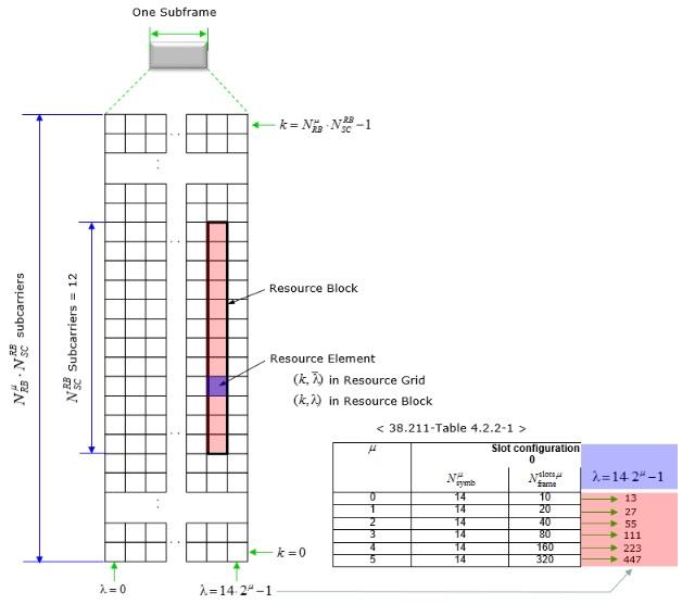
- A resource grid is allocated for a given antenna port (p), subcarrier spacing configuration and transmission direction (downlink or uplink).
- A resource grid consists of a number of Resource Blocks (RBs) for one subframe.
- Each RB has 12 consecutive subcarriers in the frequency domain.
- A “Resource Element” (RE) spans 1 subcarrier in the frequency domain and 1 OFDM symbol in the time domain. Thus, an RB contains one or many REs.
-
Each element in the resource grid for antenna port (p) and subcarrier spacing configuration (μ) is called a resource element and is uniquely identified by (k,l) p,μ where k is the index in the frequency domain and “l” refers to the symbol position in the time domain relative to some reference point. Resource element (k,l) p,μ corresponds to a physical resource and the complex value a k,l p,μ .
-
Figure-1 depicts concept of resource grids, resource blocks and resource elements applied in LTE and 5G NR wireless systems.
Antenna Ports Mapping to Physical Antennas
- As shown in the physical layer below, antenna ports are logical ports which lies before and after precoding module.
- The number of layers in the physical layer is less than or equal to the number of antenna ports.
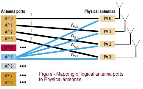
- Figure-2 depicts the relationship (mapping) between antenna ports and physical antennas.
- One antenna port can be mapped to a single physical antenna, or to multiple physical antennas.
- This means modulated data symbols can be sent to one or multiple physical antennas.

-
As shown in the figure-3 , modulated data symbols from all the layers are combined and re-distributed to each of the antenna ports before pre-coding module.
-
After precoding algorithms are applied each of the precoded data symbols goes through separate REs (Resource Elements). This is shown by multiple RE mapper modules.
-
Independent resource grids are created separately for each of the antenna ports before the IFFT operation during OFDM signal generation.
-
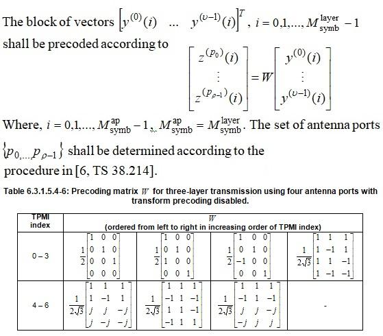
Section “6.3.1.5 Precoding” in 3GPP TS 38.211 describes various Precoding matrix tables used for different combinations of (layers, antenna ports) as follows. One such table is mentioned below.
- Single layer/Two layer/Three layer/Four layer
- Two antenna ports/Four antenna ports
Note: Here for simplicity, “number of columns” refer to number of layers in a physical layer where as “number of rows” refer to number of antenna ports.
References:
- 3GPP TS 36.211 LTE
- 3GPP TS 38.211 5G NR (Physical channels and modulation)
Advertisement


