VSAT Installation Guide: Step-by-Step with Block Diagram
Advertisement
Installing a VSAT (Very Small Aperture Terminal) system is essential for establishing reliable satellite communication, especially in remote areas. A proper installation ensures optimal performance, minimizing signal interruptions and maximizing data transmission. This guide provides a comprehensive step-by-step walkthrough to help you set up your VSAT system efficiently, from equipment assembly to final alignment and activation.
We will also go through a detailed breakdown of the VSAT system block diagram, illustrating how each part functions in satellite communication.
What is VSAT?
VSAT is a satellite communication system that uses small dish antennas to provide internet and data services, especially in remote areas. It enables reliable two-way data transmission between remote terminals and a central hub via satellites.
As we know, satellite communication uses satellites placed above the earth for communication by VSATs placed on the earth. It is also used for TV broadcasting. Satellites use microwave frequencies for communication with each other using inter-satellite links and with earth stations or VSATs. There are different types of satellites based on applications and their orbits.
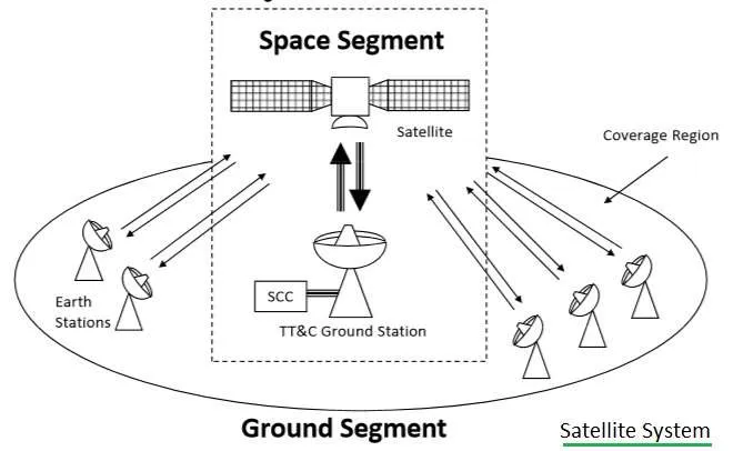
The figure above depicts a typical satellite system. As shown, it consists of a space segment, a ground segment, and a TT&C (Tracking, Telemetry & Command station OR satellite control center).
Duplexing techniques such as FDD/TDD and multiple access techniques such as FDMA/TDMA/CDMA are used to separate signals. This helps in the efficient usage of satellite transponder bandwidth.
Basics of Satellite Communication
The following table mentions band versus various frequency range used in RF or wireless communication.
| Band | Frequency Range |
|---|---|
| L | 1-2 GHz |
| S | 2-4 GHz |
| C | 4-8 GHz |
| X | 8-12.5GHz |
| Ku | 12.5 to 18 GHz |
| K | 18 to 26.5 GHz |
| Ka | 26.5 to 40GHz |
VSAT Frequency Bands
A satellite is basically composed of three main parts: a transponder, antenna systems, and solar cells. The transponder converts a higher frequency received from Earth to a lower frequency and transmits it back to Earth. For the C band as mentioned below, it converts 6.175 GHz to 3.950 GHz as a 2225MHz LO is used in the satellite.
The various VSAT frequency bands used in VSAT satellite communications are as follows. Here, uplink refers to Earth Station to Satellite, whereas downlink refers to Satellite to Earth Station.
| VSAT band | Uplink/Downlink frequency range |
|---|---|
| L Band | Uplink: 1.6265 GHz to 1.6605 GHz ; Downlink: 1.525 GHz to 1.559 GHz |
| C Band | Uplink : 5.925 to 6.425 GHz; Downlink : 3.700 to 4.200 GH |
| Extended C Band | Uplink : 6.725 to 7.025 GHz; Downlink : 4.500 to 4.800 GHz |
| Ku Band | Uplink : 14.000 to 14.500 GHz; Downlink : 10.950 to 11.700 GHz |
| Ka Band | Uplink: 27.5 GHz to 31 GHz ; Downlink: 17.7 GHz to 21.2 GHz |
VSAT System Block Diagram
Very Small Aperture Terminal (VSAT) refers to an earth station linked to a satellite using an RF link and usually has different diameter antennas. VSATs provide the important communication link to set up a satellite-based communication network. VSATs can be used for voice, data, or video transmission and reception.
The VSAT comprises two modules: an outdoor unit and an indoor unit. The outdoor unit mainly houses the antenna, feed horn, RF Transceiver, LNA, and Power amplifier.
The antenna size is typically 1.8 or 2.4 meters in diameter, although smaller antennas are also in use. The indoor unit functions as a mux-demux, modem, and interfaces with the end-user equipment like PCs, LANs, Telephones, or an EPABX.
The following diagram describes a typical schematic consisting of various VSAT subsystems.
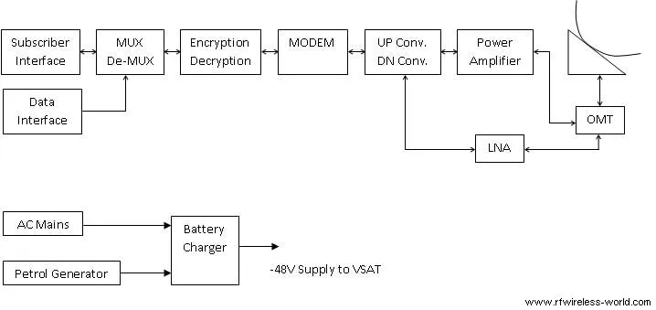
VSAT Outdoor Unit (ODU)
The Outdoor unit is usually mounted near the antenna systems outside, hence the name. It consists of RF frequency converters (Up/Down converter), Power Amplifier, Low Noise Amplifier (LNA), OMT, and Antenna system.
- The Up/Down converters convert frequencies IF to RF frequencies and vice versa. For example, an Up converter converts 70MHz to 6175 MHz and a Down converter converts 3950MHz to 70MHz for C band application.
- The Power Amplifier will amplify the signal before transmitting to the feed horn of the Antenna system.
- LNAs are designed to amplify the noise added received signal received from the satellite. It is designed such that it will amplify the signal and not the noise. Noise temperature defines LNA performance.
- The Antenna system houses the reflector, feed horn, mount, and cables. VSAT antennas usually vary from 1.8 meters to 2.4 or 3.8 meters. The feed horn is mounted at the focal point of the antenna. The feed horn guides transmitted power towards the antenna dish and will go to the medium consecutively. It also collects the received power from the dish and will enter into the LNA.
- The feed horn is made of an array of microwave passive components.
- The outdoor unit is connected through a coaxial cable to the indoor unit, which is situated inside the room/building. The length of the cable is usually about 300 feet (approx. 90 meters).
VSAT Indoor Unit (IDU)
The IDU consists of MUX/DEMUX, EDU (Encryption Decryption Unit), modem (modulator-demodulator).
- MUX will interface with end-user equipment viz. telephone, computers, and sometimes with EPABX and LAN or router if it has to carry more information. MUX will multiplex all the channels connected with it using TDM. On the receiver side, DEMUX is used to de-multiplex the channels and passed on to respective end-user equipment.
- EDU is basically the Encryption-Decryption unit which provides security by modifying the information to be transmitted. On the receiver side, the encryption technique will be conveyed so that the information can be retrieved back again.
- The MODEM basically performs modulator-demodulator functionality on the transmit and receive sides respectively.
- The Modulator inserts information on the intermediate frequency (IF), usually called the carrier. This is done based on the modulation scheme set. Usually, the QPSK scheme is used in satellite communication. Forward Error Correction is also employed in the modem which enhances the BER for the same transmitter power usually used in non-FEC systems.
- In order to communicate between VSAT 1 and VSAT 2, the modulator frequency of VSAT 1 and the demodulator frequency of VSAT 2 need to be the same and vice versa to complete the full duplex communication channel. Based on VSAT frequency assignments as per FDMA, frequency settings in various modems and RF transceivers are set appropriately.
VSAT Installation Procedure
Let us understand the step-by-step procedure for VSAT installation.
Step 1: Open all the subsystems from the received boxes. Subsystems include Antenna and accessories, Feed Horn, OMT, BUC, LNB, Satellite Modem, MUX, EDU.
Step 2: Mount Antenna along with support. Do not tighten all the screws.
Step 3: Check satellite latitude and longitude with which VSAT has to be tuned. Calculate Azimuth and Elevation required for antenna alignment using calculators available by inputting the latitude and longitude of the place where the VSAT needs to be installed.
If calculators are not available, one can calculate the required azimuth and elevation angles for pointing an antenna towards a Geo satellite using the latitude of the site, the longitude of the site, and the equatorial longitude of the satellite as mentioned below:
First, calculate angle Beta and path length L.
- Beta= cos -1 (cos[Dl].cos[la])
Where,
“Dl” is the difference between the longitude of the Earth Station and the Satellite.
“la” is the earth station latitude
L=(18.2- 5.4 cos[Beta])x 10 4 Km
Elevation Angle = cos -1 [ 4.22 x (10 4 /L)][sin(Beta)]
Azimuth = [ 180degree + tan -1 (tan(Dl)/sin(la)) ]
Step 4: Adjust Antenna Azimuth using a compass and also elevation using tools available. If tools are not available, roughly place the antenna and first complete all other steps as mentioned below. Then, connect the spectrum analyzer at IF OUT of LNB and check for a good signal, and tighten the antenna in that position.
Step 5: Run the IF cables from LNB and BUC to the indoor unit (satellite modem). Connect the LNB cable to IF IN of the modem and BUC to IF OUT of the modem.
Step 6: Do necessary connections between MUX and the Satellite modem for the Data (or voice or voice plus Data) to be transmitted using the satellite link.
Step 7: Connect MUX with EPABX for voice connection and with PC for data connection depending on the system designed for.
Step 8: Do the settings for the appropriate VSAT frequency and power in RF equipment (RF Transceiver unit) and modem.
The following settings need to be done in the IF Modem for VSAT 1 and VSAT 2 to be communicated via satellite. Need to take care of Bandwidth so that one spectrum does not overlap the other.
VSAT FREQUENCY SETTINGS with example
Following are the typical VSAT frequency settings at modems and RF transceivers units applied for VSAT installation. This establishes VSAT to VSAT communication via satellite.
| VSAT System Equipment | VSAT#1 settings | VSAT#2 settings |
|---|---|---|
| Satellite modem (from Comtech Telecommunications Corp.) | Modulator Frequency : 71.1MHz Demodulator Frequency : 71.2MHz | Modulator : 71.2MHz Demodulator : 71.1MHz |
| RF Tranceiver Unit ODU (from Comtech Telecommunications Corp.) | Up Converter (UC) : 6176.1MHz Down Converter (DC) : 3951.2MHz | UC: 6176.2MHz DC: 3951.1MHz |
Typical VSAT system specification
- Access is TDM-QPSK-FDMA
- Information rate 128kbps
- Hub station antenna 11 meters or 7.5 meters
- VSAT antenna 2.4 meters, 5-watt PA, 65 deg K LNA
- Rate 1/2 Convolution FEC, Viterbi soft decision decoder, and outer Reed Solomon encoder-decoder
- Support for 5-7 voice channels, Data channel for Network Management
- Frequency of operation -C band
Conclusion
By following the steps outlined in this guide, you can successfully install and activate your VSAT system, ensuring stable and reliable satellite communication. As mentioned in the VSAT system block diagram, each component, from the outdoor unit to the indoor modem, plays a significant role in delivering high-quality wireless connectivity.