 RF
RFL Band Satellite Modem Design and Block Diagram
Advertisement
This page describes the design of an L Band Satellite modem, complete with a satcom modem block diagram. We’ll explore the modulation and demodulation processes within a satellite modem operating at L Band frequencies, providing a step-by-step guide for its design. As this modem facilitates satellite communication, it’s also known as a satcom modem. The frequency band for this modem typically ranges from 950 to 1450 MHz.
The satellite modem finds its place in earth stations or VSAT stations, providing voice and data connectivity to remote areas via satellite networks. On one side, the satellite modem connects with a Multiplexer/Demultiplexer, and on the other side, it interfaces with an RF Transceiver.
The RF transceiver must support L band Up converters and L band Down converters to seamlessly interface with the L band satellite modem. The Multiplexer combines numerous small bandwidth voice and data channels into a high bandwidth baseband channel. This combined channel then serves as input to the satellite modulator, which modulates it onto a carrier using a chosen modulation scheme.
Conversely, the Demultiplexer extracts the high bandwidth baseband channel from the satellite demodulator, splitting it into smaller, low bandwidth channels that connect to telephones or computers.
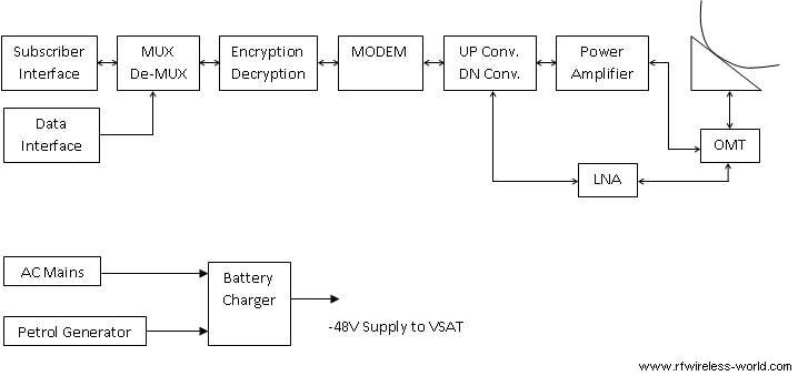
The transceiver used here converts L band to C band/Ku band and vice versa in transmit/receive path.
The following satcom modem block diagram illustrates the modulator and demodulator components of a satellite modem. In VSAT systems employing an L-band modem, the RF Transceiver operates at L band. In this RF transceiver, the up converter shifts the L band signal to the C band frequency, while the down converter transforms the C band signal back to L band. Here, L band refers to frequencies within the range of 950 to 1450 MHz, whereas C band covers 5925 to 6425 MHz in the uplink and 3700 to 4200 MHz in the downlink direction.
L Band Satcom Modem Block Diagram
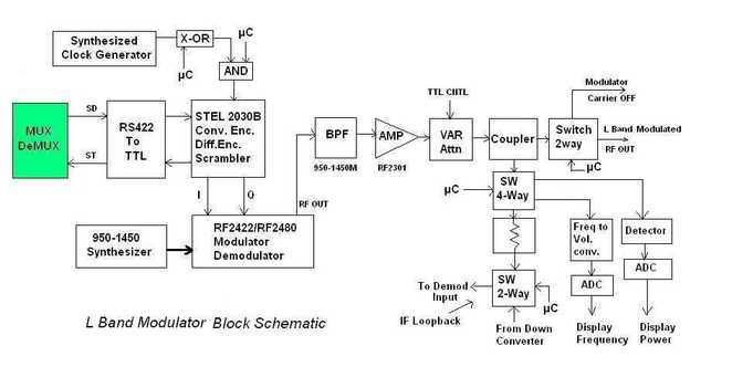
Figure-1: L Band Satellite modem Block diagram (Modulator part)
As depicted in the modem block diagram, it comprises two main cards: an M&C Card and a modulator/demodulator card.
The M&C Card houses a Micro-Controller (DS80c320), EPROM, NVRAM, and various discrete components.
The modulator/demodulator card is a multi-layer mixed-signal board containing a Direct Digital Synthesizer (AD9851), STEL2030C (Encoder-Decoder), RF2480/RF2422 Modulator, AD558 (D to A Converter), SPDT switch (AS164-80 from Alpha industries), 20dB Coupler (using Micro-strip), FS-PLL-S-A02 Synthesizer, ALPHA variable attenuator (in 1 dB and 0.5dB steps), a reference Oscillator card, a MMIC amplifier (MSA1104), and other SMD components.
The M&C Card monitors and controls various parameters of the satellite modem’s modulator and demodulator sections. It includes an RS485 interface for remote operation. The software is embedded within the EPROM on the M&C Card.
L Band Satellite Modem Design
This satcom modem has been crafted using discrete components, as detailed in the modulator section of the satcom block diagram above.
An L band filter, designed using L and C components, is inserted after the modem IC. This filter ensures the removal of unwanted carriers.
Attenuators are incorporated to manage the power level in both the modulator and demodulator sections.
A crystal oscillator provides the reference clock and serves as a reference for the synthesizer. The synthesizer then selects the frequency within the L band, with a step size as designed.
AND gates are strategically placed at various points to enable ON/OFF functionality.
The following parameters are designed to be monitored and controlled on this satellite modem:
Modulator Part
- Transmit Frequency
- Power Level
- Modulator ON/OFF
- Modulation type selection (BPSK/QPSK)
- Data rate
- Differential Encoder ON/OFF
- Scrambler ON/OFF
- Modulator data (inverted/Normal)
- Modulator clock source and phase
- Modulator alarms
- Modulator pure carrier mode
Demodulator Part
- Receive Frequency
- Demodulator input power level
- Demodulation type
- Data rate
- Data type inverted/Normal
- Differential Decoder ON/OFF
- Descrambler ON/OFF
- Demod clock source and phase
- Demod Eb/N0
- Demod BER
- Demod Alarms
As mentioned earlier, the M & C card, built around a Micro-controller circuit, manages and monitors these parameters. The setup also includes a discrete board (using digital ICs) and an RF board (based on microstrip design principles).
Satellite modem ICs are available from various manufacturers, housing multiple modulator and demodulator features. Employing these ICs can reduce size and cost. Nowadays, the entire Satellite modem physical layer can be implemented on a DSP (Digital Signal Processor), further minimizing the time and cost involved in satellite modem design and development.
Advertisement


