 RF
RFCPRI Protocol Stack in RRH
Advertisement
The Common Public Radio Interface (CPRI) protocol stack is a crucial component in modern wireless communication systems. Widely used in Remote Radio Heads (RRH), it facilitates efficient and reliable data exchange between the RRH and the baseband unit (BBU).
This article explores the structure, layers, and significance of the CPRI protocol stack, ensuring seamless connectivity in mobile networks. As mentioned in the article on CPRI frame structure, CPRI interface lies between REC and REs in RRH system architecture. CPRI interface covers two layers: layer-1 (physical layer) and layer-2 (data link layer).
The figure below depicts CPRI protocol stack mentioning these layers.
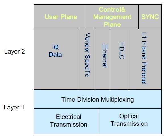
The CPRI interface supports the following information types:
- IQ Data: User plane information in the form of in-phase and quadrature phase modulation data (i.e. digital baseband signals).
- Synchronization data: Used for frame and time alignment.
- L1 Inband Protocol: Signalling information that is related to the link and is directly transported by the physical layer. This information is required, e.g. for system start-up, layer-1 link maintenance and the transfer of time critical information that has a direct time relationship to layer-1 user data.
- C&M data: Control and management information exchanged between the control and management entities within the REC and the RE. This information flow is given to the higher protocol layers.
- Protocol Extensions: This information flow is reserved for future protocol extensions. It may be used to support, e.g., more complex interconnection topologies or other radio standards.
- Vendor Specific Information: This information flow is reserved for vendor specific information.
CPRI Stack Layer-1 & Layer-2 functions
In RRH, the CPRI protocol stack consists of layer-1 (physical layer) and layer-2 (data link layer).
RRH protocol stack Layer-1 defines the following
- Electrical characteristics
- Optical characteristics
- Time division multiplexing of the different data flows
- Low level signalling
RRH protocol stack Layer-2 defines the following
- Media access control
- Flow control
- Data protection of the control and management information flow
Following are the functions of various protocol data planes:
The following data flows can be discerned:
- Control Plane: Control data flow used for call processing.
- Management Plane: Management information for the operation, administration and maintenance of the CPRI link and the RE.
- User Plane: Data that has to be transferred from the radio base station to the mobile station and vice versa. These data are transferred in the form of IQ data.
- Synchronization: Data flow which transfers synchronization and timing information between REC and RE.
The control and management plane will be mapped to a single information flow over the CPRI link.
User plane data
The user plane data are transported in the form of IQ data. Several IQ data flows will be sent via one physical CPRI link.
Here each I/Q data represents per carrier and it is for one antenna. It is referred to as antenna carrier.
- Antenna-carrier (AxC): One antenna-carrier is the amount of digital baseband (IQ) U-plane data necessary for either reception or transmission of one UTRA-FDD carrier at one independent antenna element.
- AxC Container: It contains the IQ samples of one AxC for one UMTS chip duration.
- Service Access Points: For all protocol data planes layer 2 services access points are defined that will be used as reference points for performance measurements. These service access points will be denoted as SAPCM, SAPS and SAPIQ.
- Downlink: Direction from REC to RE.
- Uplink: Direction from RE to REC.
The table below describes the functions of REs and REC entities in a RRH (Remote Radio Head).
| Functions of REC | Functions of RE |
|---|---|
| Downlink | Downlink |
| Radio Base Station Control and Management | D/A conversion |
| lub Transport | Channel Coding |
| RRC Channel Filtering | Up Conversion |
| lub Frame protocols | Interleaving |
| ON/OFF control of each carrier | |
| Spreading | |
| Carrier Multiplexing | |
| Scrambling | |
| Power amplification and limiting | |
| Adding of physical channels | |
| signal distribution to signal processing units | |
| Antenna supervision | |
| Transmit power control of each physical channel | |
| RF filtering | |
| Frame and slot signal generation(including clock stabilization) | |
| Uplink | Uplink |
| A/D conversion | Channel Decoding |
| Down Conversion | Deinterleaving |
| AGC | Despreading |
| Carrier De-multiplexing | Descrambling |
| LNA | Transmit power control & feedback information detection |
| RF filtering | Measurements |
| Measurements |
Conclusion
The CPRI protocol stack serves as a backbone for RRH functionality, enabling robust and efficient communication within wireless networks. Its layered design and optimized performance play a pivotal role in meeting the growing demands for high speed and low latency communication, making it an indispensable part of modern mobile infrastructure.
Advertisement


