 RF
RF1 GHz Hairpin Bandpass Filter Design
Advertisement
This article explains the design of a 1GHz Hairpin type Band Pass Filter (BPF). You can use RF design software tools like Agilent ADS or Microwave Office to simulate and verify the results. The layout is created automatically.
RF Simulation Circuit
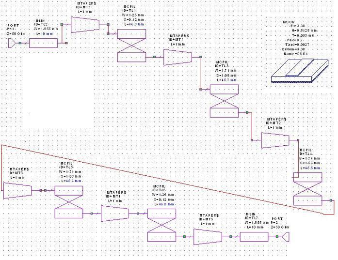
The figure above depicts the RF simulation circuit for a 1GHz Hairpin BPF.
Substrate Specifications
The following table outlines the substrate specifications used in the design:
| Substrate Specifications | Value |
|---|---|
| Relative Dielectric Constant (εr) | 3.38 |
| Substrate Thickness (H) | 0.8128 mm |
| Conductor Thickness (T) | 0.035 mm |
| Rho (Metal Bulk resistivity normalized to gold) | 0.7 |
| Tand (Loss tangent of dielectric) | 0.0027 |
Results
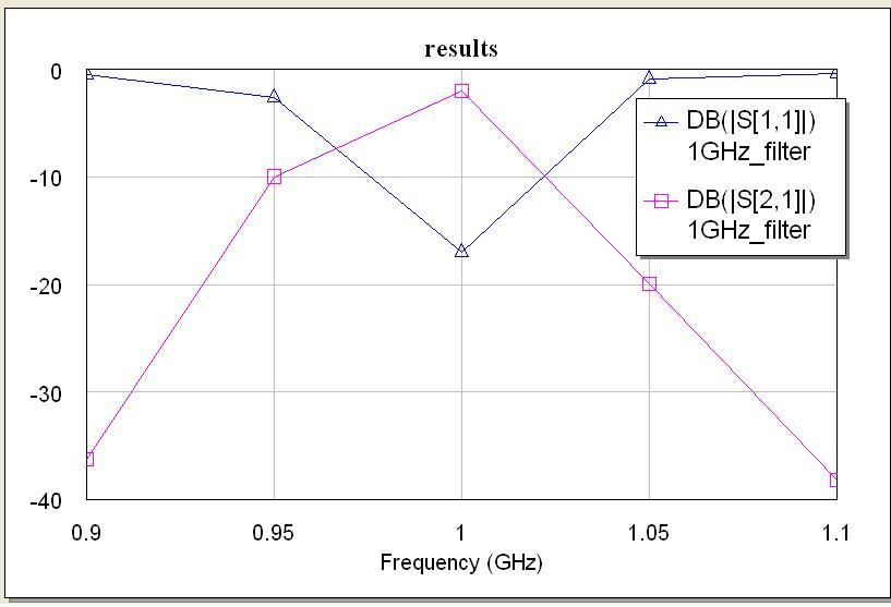
As shown in the figure, S21 (insertion loss) is about 0 dB. At an RF frequency of 1GHz, the insertion loss of the BPF (Band Pass Filter) is approximately -2dB. The return loss of this filter (S11) is around -17dB.
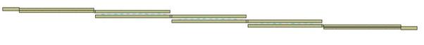
Layout Schematic
Conclusion
As explained, any other RF filter of hairpin or interdigital type can be designed and simulated using this approach.
Advertisement


