RF Multipath Channel Simulator: Basics and Applications
Advertisement
This page covers RF multipath channel simulator basics with a block diagram. It also mentions an RF multipath channel simulator application note.
Simulator: It is the software or hardware, or both, that implements a real-time scenario to help in product testing without putting the product in a real environment. This helps the product go through successful operational performance once put in the actual conditions for which it has been designed or developed.
Channel Simulator: The simulator that incorporates the effect of a real-time channel is known as a channel simulator. It introduces delay, attenuation, fading, noise, Doppler shift, etc., to the signal of the device under test.
Multipath Channel Simulator: It introduces the effect of multiple paths to the signal. The number of paths needs to be software or hardware configured based on the test scenario as per the application. This is because, as we know, the transmitted signal passes through different paths and will incur reflection from multiple objects (buildings, towers, etc.) during travel until it reaches the receiver end. Hence, we find multiple copies of the transmitted signal at the receiver, each having different attenuation and delay. This real-time effect is simulated in a multipath channel simulator.
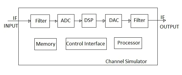
Figure-1 depicts the implementation of the RF/IF multipath channel simulator. As shown, it operates at IF frequency. In order to use the multipath channel simulator at RF frequencies, optional RF down converter and RF Up converter modules are needed. In this case, the RF signal of the DUT (Device Under Test) is fed to the RF Down converter and the downconverted IF signal is then fed to the channel simulator input. The IF output from the channel simulator is converted back to RF using RF upconversion and fed back to the DUT.
- Filter: This bandpass filter is used to limit the frequency as input. It’s designed based on the bandwidth of interest and the rejection needed in the stop band of frequencies.
- ADC: It converts a signal in analog form to digital form for digital signal processing.
- DSP: This will house advanced signal processing software to emulate the effect of a real-time channel, including a multi-path scenario. The software is programmable as per various user-defined input parameters through the front panel or remote terminal.
- DAC: It converts the channel-impaired digital signal back to analog form in order to interface with an analog filter.
- Filter: It is a bandpass filter which removes all the unwanted frequencies that might have been introduced in the signal due to ADC/DAC processing as well as DSP processing. It passes the proper IF bandpass signal for test purposes.
For testing which requires additional signals, such as interference testing, optionally one more signal generator is required and the signals are combined using an RF power combiner before feeding to the multipath channel simulator. This will help in multi-channel testing.
RF Multipath Channel Simulator Application Note
Real Time Logic, Inc. has launched the Multipath Channel Simulator model T400CS. It is useful for modem testing as well as transmitter/receiver testing.
This channel simulator has the following features:
- Operates on various frequency bands such as UHF band, L band, S band, C band, X band, and Ku band etc.
- Simulates different types of satellites e.g. LEO, MEO, GEO etc.
- Suitable for testing OFDM as well as continuous wave signals.
- Simulate up to 8 signals with individual impairments and configurations. The parameters which are configured include modulation type, frequency offset, data rate, PRN code, amplitude, filtering etc.
- Built-in spectrum signal analyzer which also provides BER, C/No, and Eb/No display. It can analyze both time domain and frequency domain waveforms.
- Supports different versions to support different bandwidth options (40MHz, 85 MHz, 250 MHz) etc.