Arduino pH Sensor Interface: Diagram, Working, and Code
Advertisement
This application note explains how to interface an Arduino board with a pH sensor, including the necessary diagram, working principles, and Arduino code.
Introduction
pH sensors are essential in chemical labs for acidity testing, determining the nature of a liquid. Traditional acidity tests can be time-consuming. However, interfacing a pH sensor with an Arduino board significantly speeds up the measurement process. This note will guide you through the process.
About the pH Sensor
A pH sensor detects the hydrogen ion (H+) concentration in a liquid, indicating its acidity or alkalinity. When immersed in a liquid solution, smaller ions penetrate the boundary of the glass membrane, while larger ions remain in the solution. This creates a potential difference.
The pH meter measures this potential difference between the electrodes. As shown in the diagram, the pH sensor’s output is connected to an analog read input on the Arduino board. The sensor provides different analog outputs for different liquid solutions. By calibrating with a known solution like water, you can determine the pH value of other liquids. You can also construct a pH meter with a display by interfacing an LCD with the Arduino and the pH sensor.
About the Arduino Board
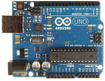
 Arduino board
- The Arduino Uno features an ATmega328 microcontroller from ATMEL. This microcontroller includes 32 KB of flash memory, 2 KB of RAM, an 8-bit CPU, and 1 KB of EEPROM.
- It offers 6 analog pins that read voltage (not current) and convert analog measurements to digital for various purposes.
- It also provides digital pins (0 to 13) that can function as either input or output.
- It has various interfaces such as I2C, digital pins, analog pins, serial communication, and USB.
- It also includes a reset pin, power port, crystal oscillator, and Tx/Rx LEDs.
- This open-source prototype board can be easily programmed using the Arduino IDE and a USB connection between your laptop/PC and the Arduino board.
- The IDE uses a simplified C++ program.
- The board requires 5V DC, which can be supplied using an AC/DC adapter or battery.
Arduino Interfacing with pH Sensor Diagram and Working
As shown in Figure 1, the three pins of the pH sensor are connected to the Arduino board. The pH sensor used here is from an ORP Meter.
 Arduino Interfacing with pH sensor
Here are the connections between the pH sensor and the Arduino board:
- Vcc (+ pin of pH sensor side) - 5V (Arduino side)
- GND (- pin of pH sensor side) - GND (Arduino side)
- OUT (A pin of pH sensor side) - A1 (Arduino side)
Arduino pH Sensor Interface Code
The following Arduino code is compiled and uploaded to the Arduino board using the Arduino IDE. This code is used for testing a pH sensor-based ORP meter. It provides pH sensor readings on the Arduino Serial Monitor.
#define VOLTAGE 5.00    //system voltage
#define OFFSET 0        //zero drift voltage
#define LED 13         //operating instructions

double orpValue;

#define ArrayLenth  40    //times of collection
#define orpPin 1          //orp meter output,connect to Arduino controller ADC pin

int orpArray[ArrayLenth];
int orpArrayIndex=0;

double avergearray(int* arr, int number){
  int i;
  int max,min;
  double avg;
  long amount=0;

  if(number<=0){
    Serial.println ("Error number for the array to avraging!/n");
    return 0;
  }
  if(number<5){   //less than 5, calculated directly statistics
    for(i=0;i Serial.print("ORP: ");
    Serial.print((int)orpValue);
    Serial.println("mV");
    digitalWrite(LED,1-digitalRead(LED));
  }
}
Reference
Conclusion
This application note has demonstrated how to interface a pH sensor with an Arduino Uno board. Arduino boards are also used for interfacing with various other types of sensors for a wide range of applications. Common sensors interfaced with Arduino include sound sensors, gyro sensors, LDR sensors, GPS sensors, color sensors, and heartbeat sensors.
Advertisement
 RF
RF


