5G OTA Testing Basics and Solutions
Advertisement
This app note covers OTA (Over-The-Air) testing basics. It mentions 5G OTA testing requirements as per the 5G NR standard and describes Rohde & Schwarz solutions for OTA testing.
Introduction
The 5G NR (New Radio) system is the latest in the 3GPP series of wireless cellular technologies, designed to deliver very high data rates in both uplink and downlink directions. To address this requirement, 5G base stations (gNB) and mobile phones use massive MIMO antenna arrays. This helps in achieving high capacity and high energy efficiency. 5G base stations use separate RF front ends for each of the antennas used in the array.
The RF front end consists of an RF transceiver, RF power amplifier, up-converter, down-converter, etc.
5G NR supports various use cases, viz., eMBB (enhanced Mobile Broadband), URLLC (Ultra-Reliable Low Latency Communications), and mMTC (massive Machine Type Communications).
The measurements are categorized into conducted and radiated. Conducted measurements use cables or wires, whereas radiated measurements are performed over the air using EM (Electromagnetic) wave transmission and reception.
What is OTA (Over The Air)?
Radiated tests are performed Over the Air without any cables/wires. They are categorized into two major tests: near field and far field, based on the distance between the measurement system and the DUT (Device Under Test, i.e., UE or gNB).
The region up to a distance of is known as the near-field region, whereas the distance above is known as the far-field region. Here, D is the antenna diameter and is the wavelength.
In the near field, power decay follows the equation, whereas in the far field, power is proportional to from the origin towards the far end of the antenna. Hence, in the near field, power intensity falls off very rapidly as we measure away from the source.
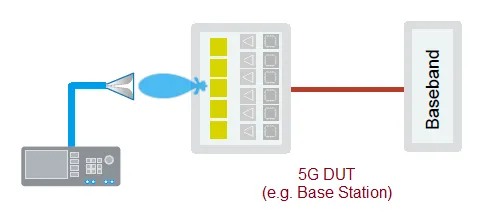 Image Courtesy: Rohde & Schwarz
Figure 1 depicts a 5G OTA testing setup from Rohde & Schwarz. The setup uses an R&S spectrum analyzer.
5G OTA Testing
The 5G NR RAN working group is working on radio performance and protocol testing under a series of standards, TS 38.101 to 38.307. This group is responsible for finalizing the minimum requirements for radio and protocol conformance testing during transmission and reception. The standard defines EMC requirements, radio link test requirements, cell selection/re-selection, performance tests, and so on.
OTA testing should cover both the frequency bands (FR1 and FR2) supported by 5G NR devices. FR1 ranges from 450 MHz to 6 GHz, and FR2 ranges from 24.25 to 52.6 GHz. FR1 and FR2 use bandwidths of 100 MHz and 400 MHz, respectively.
Following are the OTA test methods finalized for 5G NR UE devices:
- rect Far Field (DFF)
- direct Far Field (IFF)
- ar Field to Far Field Transformation (NFTF)
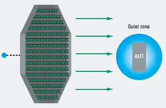 Image Courtesy: Rohde & Schwarz
Figure 2 depicts the PWC200 (Plane Wave Converter) from Rohde & Schwarz. It consists of a bidirectional phased array with 156 Vivaldi antennas. It is housed in a compact test chamber to perform real-time transmitter and receiver measurements.
To feed the signal to the array or to test the signal reception part, a combiner is used. The power combiner merges all signal paths to a single port where the test instrument is connected.
R&D measurements include gain, radiated power (ERP or EIRP or TRP), receiver sensitivity, transceiver characterization, beam steering & beam tracking, etc. Production tests mainly include functional tests and calibration, etc.
The following table mentions transmitter and receiver tests as part of transceiver characterization.
| Device and Test type | Description of test cases |
|---|---|
| UE Radiated Transmitter Tests | • Transmitter power • Output power dynamics • Transmit signal quality • Output RF spectrum emissions • Spurious emissions • EVM |
| Base Station Radiated Transmitter Tests | • Radiated transmit power • Base station output power • Output power dynamics • Transmitted signal quality (EVM) • Occupied bandwidth • Adjacent channel leakage ratio(ACLR) • Operating band unwanted emissions • Transmitter spurious emissions • Transmitter intermodulation |
| UE Radiated Receiver Tests | • Diversity characteristics • Reference sensitivity power level • Maximum input level • Adjacent channel selectivity • Blocking Characteristics |
| Base Station Radiated Receiver Tests | • Sensitivity • Dynamic range • In-band selectivity and blocking • Out-of-band blocking • In-channel selectivity |
R&S solutions for 5G OTA Testing
The following table mentions solutions from R&S for 5G OTA testing.
| R&S Solution | Description |
|---|---|
| CTIA OTA (TS8991/WPTC) | • Frequency: 0.4 to 18 GHz • Minimum Size: 250 x 250 x 220 cm • Fields: Near & Far • Signals: Modulated/CW • Parameters: EIRP, EiS, Gain, EVM etc. |
| OTA R&D (WPTC Spiral Scanner) | • Frequency: 0.4 to 40 GHz • Minimum Size: 250 x 250 x 220 cm • Fields: Near & Far • Signals: Modulated /CW • Parameters: EIRP, EiS, Gain, EVM etc. |
| OTA R&D and Production (ATS1000) | • Frequency: 0.4 to 90 GHz • Minimum Size: 85 x 100 x 180 cm • Fields: Near & Far • Signals: Modulated /CW • Parameters: EIRP, EiS, Gain, EVM etc. |
| OTA R&D (DST 200) | • Frequency: 0.4 to 40 GHz • Minimum Size: 77 x 76 x 70 cm • Fields: Far Field (UEs) • Signals: Modulated / CW • Parameters: EIRP, EiS, Gain, EVM etc. |
| OTA Production (NRPM OTA Power Sensors) | • Frequency: 28 to 75 GHz • Minimum Size: 45 x 40 x 48 • Fields: Near & Far • Signals: Modulated / CW • Parameters: EIRP at single points |
| PWC200 (Plane Wave converter) | • Frequency: 2.3 to 6 GHz • Bandwidth: 200 MHz • Dimensions: 70.86 in x 70.86 in • Quiet zone size: 100 m • EVM, EiS, EIRP, Gain, Antenna calibration etc. |
References
- 8.101 - User Equipment Radio Transmission and Reception
- 8.104 - BS Radio Transmission and Reception
- 8.141 - BS Conformance testing
Also, refer to 5G test cases and 5G test equipment from Keysight technologies.