5G NR RLC Layer: Functions, Modes, Data Structures, and RRC Parameters
Advertisement
This page provides an overview of the 5G NR RLC (Radio Link Control) layer, including its functions, modes, data structures, data transfer procedures, and related RRC parameters.
Introduction:
- RLC stands for Radio Link Control. 3GPP specification TS 38.322 defines the RLC protocol for the UE and NR radio interface.
- The RLC layer resides between the MAC layer (lower layer) and the PDCP layer (upper layer) in the protocol stack.
- Similar to previous cellular standards like WCDMA and LTE, 5G NR also supports the following RLC modes:
- Transparent Mode (TM mode)
- Unacknowledged Mode (UM mode)
- Acknowledged Mode (AM mode)
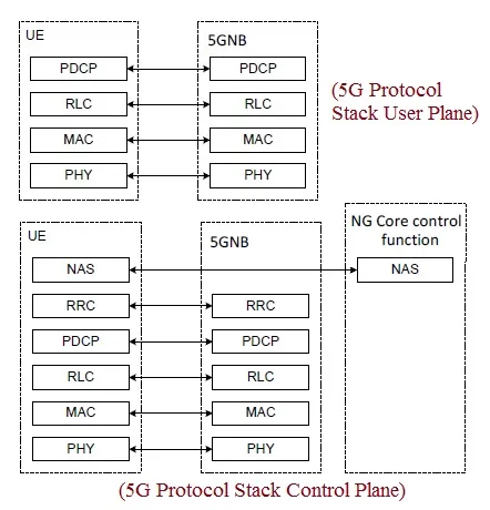 Figure 1: 5G NR Protocol Stack Layers showing the position of the RLC layer.
As shown in Figure 1, the RLC layer provides services to the upper layers and receives services from the MAC and PHY layers.
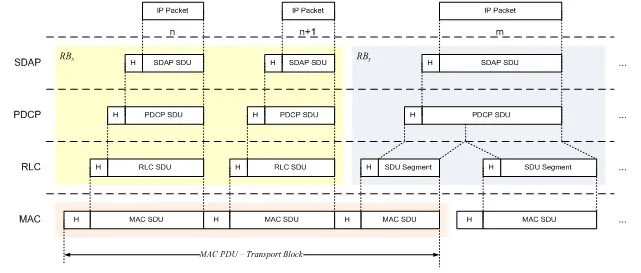 Figure 2: Data Flow Through 5G NR protocol layers.
Figure 2 illustrates the data flow through various protocol layers in the 5G NR stack.
RLC Modes: TM, UM, and AM
RLC configuration is independent of 5G NR numerologies and is associated with logical channels. The different modes are used as follows:
- TM mode: Used for SRB0, paging, and broadcast of system information.
- AM mode: Used for SRBs.
- UM or AM mode: Used for DRBs.
The ARQ (Automatic Repeat Request) procedure is supported within the RLC sublayer.
Functions of the RLC Sublayer
- Transfer of upper layer PDUs
- Sequence numbering independent of the one in PDCP (UM and AM)
- Error Correction through ARQ (AM only)
- Segmentation (AM and UM) and re-segmentation (AM only) of RLC SDUs
- Reassembly of SDUs (AM and UM)
- Duplicate Detection (AM only)
- RLC SDU discard (AM and UM)
- RLC re-establishment
- Protocol error detection (AM only)
Services Expected from the Lower Layer (MAC)
- Data transfer
- Notification of transmission opportunity
TM Mode and TM Data Transfer
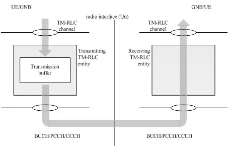 Figure 3: Transparent mode peers.
- A TM RLC entity uses logical channels such as BCCH, DL CCCH, UL CCCH, and PCCH to transmit or receive RLC PDUs.
- A TM RLC entity utilizes TMD PDUs to transmit/receive data PDUs.
- During transmission, TMD PDUs are formed directly from RLC SDUs. TM mode does not perform segmentation and adds no RLC headers to the TMD PDUs. During reception, the TM RLC entity receives TMD PDUs and forwards them to the upper layers.
UM Mode and UM Data Transfer
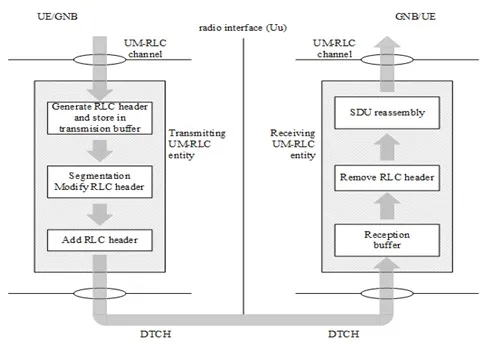 Figure 4: Unacknowledged mode peers.
- UM mode uses logical channels DL DTCH or UL DTCH.
- It uses UMD PDUs which can carry either one complete RLC SDU or one RLC SDU segment.
- The complete transmission and reception process is defined in 3GPP TS 38.322.
AM Mode and AM Data Transfer
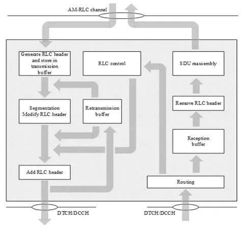 Figure 5: Acknowledged mode peers.
- An AM RLC entity uses DL/UL DCCH or DL/UL DTCH logical channels.
- It transmits and receives AMD PDUs, which can carry either one complete RLC SDU or one RLC SDU segment.
- The AM RLC entity also transmits and receives STATUS PDUs as control PDUs.
- The complete transmitting and receiving side procedures are detailed in the 3GPP 38.322 specification.
Data Structures: TMD, UMD, AMD
RLC PDU is a bit string. RLC SDUs are bit strings that are byte-aligned in length. Below are the structures for TMD, UMD, and AMD PDUs.
TMD Structure
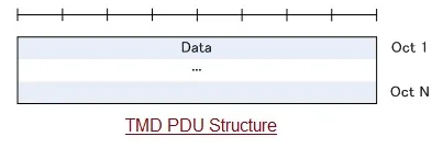 Figure 6: TMD PDU structure.
UMD Structure
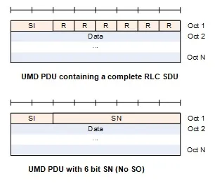 Figure 7: UMD PDU structure1.
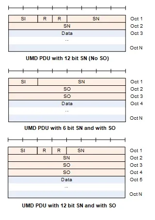 Figure 8: UMD PDU structure2.
AMD Structure
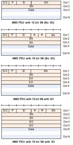 Figure 9: AMD PDU structure.
5G NR RLC Status PDU
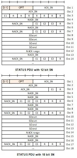 Figure 10: 5G NR RLC Status PDU.
SN (Sequence Number) Length:
- AMD PDU: 12 bits or 18 bits
- UMD PDU: 6 bits or 12 bits
SI (Segmentation Info) field:
The SI field is 2 bits in length and indicates the following:
- 00: Data field contains all bytes of an RLC SDU.
- 01: Data field contains the first segment of an RLC SDU.
- 10: Data field contains the last segment of an RLC SDU.
- 11: Data field contains neither the first nor last segment of an RLC SDU.
Other Fields:
- SO (Segment Offset): 16 bits in length.
- D/C (Data/Control): “0” indicates a control PDU, while “1” indicates a data PDU.
- P (Polling bit): 1 bit. “0” indicates “status report not requested,” while “1” indicates “status report is requested.”
- CPT (Control PDU Type): 3 bits in size. “000” indicates a “STATUS PDU,” and “001” is reserved.
RRC Parameters for RLC
The following RRC parameters are used to define the RLC layer. The Information Elements (IEs) are RLC-BearerConfig IE and RLC-config IE.
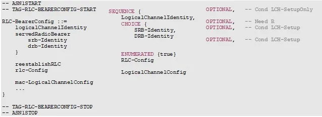 Figure 11: RLC BearerConfig IE.
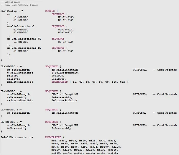 Figure 12: RLC config IE.
References
- 3GPP TS 38.322, V15.2.0 (2018-06), Radio Link Control (RLC) protocol specification (Release 15)
- 3GPP TS 38.331, V15.2.0 (2018-06), Radio Resource Control (RRC) protocol specification (Release 15)