 RF
RF555 Timer Calculator: Monostable and Astable Modes
Advertisement
555 Timer Calculator and Formula
The 555 timer IC is a cornerstone in electronics, celebrated for its simplicity, reliability, and adaptability. It shines in various modes, but it’s most famous as a monostable multivibrator and an astable multivibrator. These configurations are used to generate precisely timed pulses and square waves, respectively.
- Astable Mode (Oscillator Mode): In this mode, the 555 timer continuously generates a square wave output. It’s the go-to choice for applications like clock signals, creating tones in electronic music, and anywhere a continuous waveform is needed.
- Monostable Mode (One-Shot Mode): When set up in monostable mode, the 555 timer responds to an external trigger by producing a single, well-defined pulse. The length of this pulse is determined by external components, offering adjustable control. This mode is often used for time-delay circuits, pulse shaping, and other applications needing a single pulse.
Let’s dive into the 555 timer calculator, including calculations for both monostable and astable modes. In monostable mode, the calculator helps determine the pulse width. In astable mode, it calculates the frequency and period of the generated waveform.
555 Monostable Calculator - 1
As mentioned, this 555 timer monostable calculator figures out the pulse width based on the input resistor (R) and capacitor (C) values.
EXAMPLE #1 555 timer calculation in monostable mode:
INPUTS: R = 10 KΩ , C = 47 µFarad
OUTPUT: Output pulse width, Tp = 0.517 sec
555 Monostable Formula
Here’s the formula used in the monostable calculator #1:
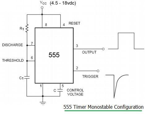
Length of output pulse or pulse width (Tp) = 1.1 *R * C
The R and C values correspond to the resistor and capacitor shown in the diagram.
555 Astable Calculator - 2
This 555 timer astable calculator determines frequency, period, high time, and low time based on the capacitor (C1) and resistor (R1, R2) inputs.
EXAMPLE #2: 555 timer calculation in astable mode:
c1=100µF, R1=R2=10 Kohm
t HIGH = 1.386 sec , t LOW = 0.693 sec, Pulse Frequency= 0.481 Hz , Pulse Period = 2.079 sec, Duty cycle = 66.67%
555 Astable Formula
Following is the 555 astable formula used in the above calculator #2.
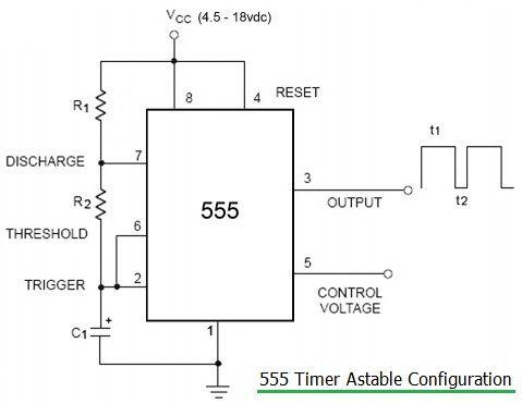
t HIGH = 0.693 *C1 * (R1 + R2) t LOW = 0.693 * C1 * R2 Pulse Frequency = 1 / (t HIGH + t LOW ) Pulse Period = 1 / Pulse Frequency Duty Cycle = (R1 + R2) / (R1 + 2 * R2)
Conclusion
In short, 555 timer calculations and formulas in both monostable and astable modes bring precision, versatility, cost-effectiveness, and educational value to electronics and circuit design. The 555 timer remains an invaluable component in the field.
Advertisement


