 RF
RF2G GSM Interfaces: BTS, BSC, MSC - Um, A, Abis
Advertisement
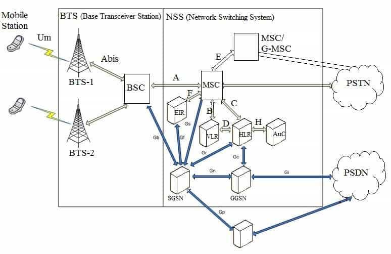
In a 2G GSM network, various interfaces connect different network elements, ensuring seamless communication and proper network functioning. The key interfaces in GSM include Um, A, Asub, and Abis, each playing a distinct role in linking the core network, base stations and mobile devices. The block diagram depicts all the GSM interfaces between GSM subsystems such as BTS, BSC and MSC.
Um Interface (Air Interface)
- Location: Between MS (Mobile Station) and BTS (Base Transceiver Station).
- Function: The Um interface, also known as the air interface, enables wireless communication between mobile phones and the BTS. It uses radio frequencies to transmit voice, data, and control signals between the mobile station (MS) and the network.
- Technology: It operates on a TDMA (Time Division Multiple Access) system and manages channel allocation, encryption, and modulation.
Abis Interface
- Location: Between BTS and BSC (Base Station Controller).
- Function: The Abis interface facilitates communication between the BTS and BSC, carrying both traffic channels (voice and data) and signaling channels. It helps control BTS functions, such as power management, channel allocation, and handovers.
- Significance: Abis is critical for managing the radio resources and ensuring the BTS and BSC communicate effectively.
A Interface
- Location: Between BSC and MSC (Mobile Switching Center).
- Function: The A interface links the BSC to the MSC, which is the core component of the GSM network responsible for switching and call management. It carries voice and signaling data, enabling call setup, handover control, and mobility management.
- Technology: It uses SS7 signaling for communication and supports large-scale call switching.
Asub Interface
- Location: Between the MSC and the Home Location Register (HLR).
- Function: The Asub interface is used for signaling between the MSC and the HLR, which stores subscriber information such as location, services, and authentication data. It helps manage subscriber data, call routing, and mobility tracking.
- Significance: The Asub interface ensures that user data is accessible for proper call routing and billing, and it facilitates authentication and roaming.
Other GSM Interfaces
The table below describes other GSM interfaces between its network elements.
| GSM interfaces | Description with position |
|---|---|
| Um | It is the air interface used between MS and BTS. It carries the GSM bursts carrying data and control information. Also referred to as Air interface. |
| A or Asub | It is used between BSC and MSC/VLR. It supports 2Mbps standard digital connection as per CCITT. |
| Abis | It is used between BTS and BSC. It supports two types of communication links viz. traffic channel at 64 kbps and signaling channel at 16 kbps. |
| B | It is used between MSC and VLR. |
| C | It is used between HLR and GMSC. Also between MSC and HLR. |
| D | It is used between HLR and VLR. |
| E | It is used between MSC and another MSC or G-MSC. |
| F | It is used between EIR and MSC and between EIR and G-MSC. |
| G | It is used between VLR and another VLR. |
Conclusion
These GSM interfaces collectively enable smooth communication across the various network elements in a 2G network system, ensuring that users can make calls, send data and move between cells seamlessly.
Advertisement


