2G GSM Call Flow and Network Entry
Advertisement
The mobile phone in GSM requires several steps, including network selection, authentication, location update, and channel allocation, ensuring secure and efficient communication between the mobile device and the network. This entry procedure is critical for enabling mobile phones to initiate and receive calls, send messages, and access network services.
In addition to the procedural details, this guide provides a comprehensive 2G GSM Call Flow Diagram to visualize the entire process.
2G Call Flow Between Mobile and Base Station
The diagram depicts GSM Call Setup; it depicts the basic flow of logical frames between BTS and MS to establish a voice/data connection. Below are the main stages of the 2G call flow.
- Mobile Station (MS) Initiation:
- The mobile phone powers on and searches for available networks.
- The MS sends a location update request to the network through the Base Transceiver Station (BTS).
- Base Station Subsystem (BSS):
- The Base Transceiver Station (BTS) forwards the location update request to the Base Station Controller (BSC).
- The BSC manages the radio resources and forwards the request to the core network (MSC/VLR).
- Mobile Switching Center (MSC):
- The Mobile Switching Center (MSC), working in conjunction with the Visitor Location Register (VLR), processes the location update request.
- The MSC initiates the authentication and ciphering process to secure communication between the mobile device and the network.
- Authentication and Ciphering:
- The MSC sends a random number to the mobile device to authenticate the SIM using the A3 algorithm. Ciphering is activated using the A5 algorithm to encrypt subsequent communication.
- Call Setup (if a call is initiated after network entry):
- The mobile station requests call setup through the Signaling Channel (SDCCH).
- The MSC establishes the call route, assigns a Traffic Channel (TCH), and sets up the voice or data communication link.
- Completion of Network Entry:
- Once authenticated and ciphered, the mobile phone is registered in the network’s Visitor Location Register (VLR) and is ready to initiate or receive calls.
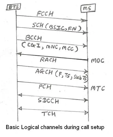 Image alt: gsm call setup
These are called initial mobile phone procedures when you power ON the phone.
-
Step-1: Mobile phone scans for carriers and determines RSSI of all and passes them to the upper layer. The upper layer decides which carrier/channel has the highest RSSI, and the mobile will lock on to that carrier.
There are two modes here: first, where the mobile has prior knowledge of broadcast carriers, and the other mode where the mobile has no prior knowledge. In the second case, the mobile has to search the entire band, while in the first case, as the mobile has broadcast carriers known, it will determine RSSI of those carriers only. Hence, it will complete the cell search operation in less time.
-
Step-2: Once the carrier is known, it will detect FB (Frequency correction Burst) on that carrier/channel, which is a pure sine wave as mentioned above of value 67.7 KHz. Any deviation from this value is determined, and this much frequency offset is corrected on the LO module by controlling through VCTCXO/VCO/OCXO used in the handset design.
-
Step-3: After correcting for Frequency offset, the mobile needs to lock on to a particular time slot on that carrier frequency in the GSM time domain frame structure.
This is done using SB decoding. 25 bits of decoded data of SCH gives reduced frame number (19 bits) and BSIC (6 bits). The reduced frame number will provide very useful information on the mobile’s physical slot in the entire hyperframe. BSIC is made of BCC (Base Station Color code - 3 bits) and NCC (Network Color code - 3 bits). The BCC field directly provides training sequence details (26 bits in size). The correlation is performed with a known training sequence to determine the peak, and hence the timing offset is determined on the received frame. Channel estimation is also performed using this training sequence.
Remember, SB comes on the same time slot as FB but after 8 time slots duration. This means time multiplexing of logical channels (FB, SB, BCCH, CCCH…) is used on the dedicated physical time slot (TS0 at Broadcast Freq).
-
Step-4: Once SB is decoded, now BCCH will appear on the same allocated physical time slot but after 8 time slot duration. BCCH is decoded, which gives useful system information (SI). Now the mobile is camped on the network, and it is ready to use voice services by exchanging useful frames/channels based on a mobile-initiated or mobile-terminated call.
If GPRS is enabled on the mobile phone, it can use data services provided by the operator.
Conclusion
The GSM mobile phone network entry procedure is fundamental to establishing a connection between a mobile device and the network. Each step, from network selection to authentication, is carefully orchestrated to ensure secure communication. The 2G GSM Call Flow Diagram illustrates how different network elements interact during this process, providing a clear understanding of how calls and data are managed in the GSM network.