SigFox Tutorial: Network Architecture, Protocol, and MAC Frame
Advertisement
SigFox is a leading LPWAN (Low Power Wide Area Network) technology designed for ultra-low-power IoT communication.
This tutorial provides an in-depth overview of SigFox’s network architecture, protocol stack, and MAC frame structure. You will learn about its key components, message flow, and the roles of MAC frame fields in uplink and downlink communication, making it easier to understand and implement SigFox in IoT solutions.
Introduction
SigFox wireless technology is based on LTN (Low Throughput Network). It is a wide area network-based technology that supports low data rate communication over larger distances. It is used for M2M (Machine-to-Machine) and IoT applications which transmit only a few bytes per day. It can be interfaced with cellular networks in order to coexist with cellular wireless technologies such as GSM, CDMA, LTE, etc.
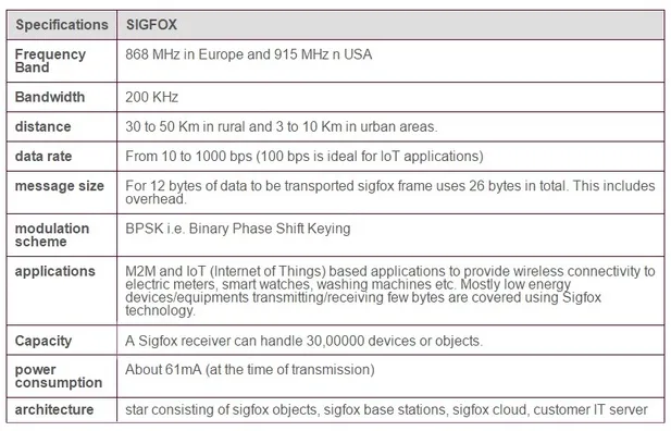
The table-1 above mentions all the sigfox system features.
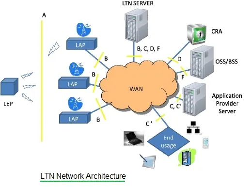
The figure-1 depicts a typical LTN (Low Throughput Network) network architecture. As shown, it consists of LEPs (LTN End Points), LAPs (LTN Access Points), a WAN or cloud part, and different types of servers. The servers include an LTN server, CRA (Central Registration Authority), OSS/BSS, and an application provider server. All these SigFox system entities are connected using various interfaces.
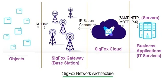
The simple SigFox network architecture is shown in figure-2. This is the same as the LTN architecture except for the terminologies used. LEPs are designated as objects, and LAPs are termed as Gateways or Base Stations. The WAN is the cloud which connects BSs (Base Stations) with business applications through different interfaces.
The transmissions from LEPs to the network (i.e., BSs or Gateways) are known as uplink transmissions. The transmissions from the network to LEPs are known as downlinks.
SigFox Protocol Stack
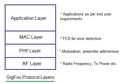
Figure-3 depicts a simple protocol stack of the SigFox wireless system. As shown, it consists of a Radio layer, Physical Layer, MAC layer, and application layer. Following are the functions of each of these layers:
-
RF Layer: This layer takes care of frequency assignment and transmit/receive power requirements at SigFox end points and base stations.
-
PHY Layer: This layer takes care of preamble insertion (at the transmit end) and removal (at the receive end). It uses BPSK modulation in the uplink and GFSK modulation in the downlink.
-
MAC Layer: It handles the management of MAC messages. It prepares frames as per uplink and downlink formats defined below. Mainly, the SigFox system is used for uplink transmissions. It can also be used for downlink transmissions using the piggybacking concept.
-
Application Layer: The different applications are supported in this LTN technology. There are various interfaces/protocols between the WAN (i.e., cloud) and servers to support the same, e.g., SNMP, HTTP, MQTT, IPv6, etc.
SigFox MAC Frame Structure
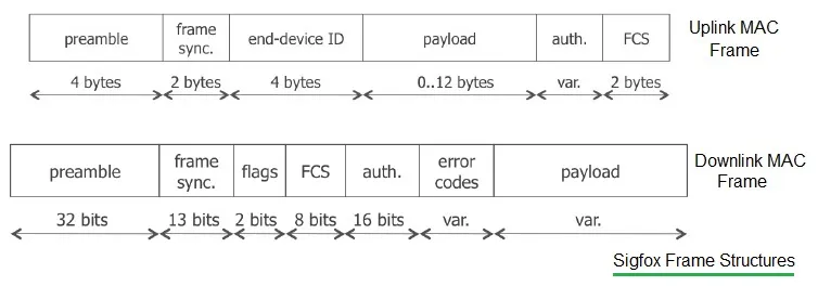
Figure-4 depicts the SigFox frame structure. It mentions both the uplink MAC frame and downlink MAC frame. As shown, the uplink frame consists of a preamble, frame sync field, end device ID, payload, authentication field, and FCS (Frame Check Sequence) field. The downlink frame consists of a preamble, frame sync, flags, FCS, authentication, error codes, and payload.
-
Preamble: The preamble is a predefined pattern of symbols used for synchronization purposes. Using this pattern, various impairments are estimated at the receiver and corrected accordingly. This has become possible as a copy of this constant pattern is known at the receiver.
-
Frame Sync Field: The frame sync field carries the frame type which differentiates different MAC frames.
-
End Device ID: The End device ID (32 bits in size) is used as a unique identifier for each of the SigFox end devices (or LEPs).
-
FCS (Frame Check Sequence) Field: The FCS field is used for error detection.
References
ETSI GS LTN 001, 002, 003 (Low Throughput Networks) documents.
Conclusion
With its simple and scalable design, SigFox enables reliable IoT communication. This tutorial equips you with the foundational knowledge needed to leverage SigFox effectively for a wide range of applications.