 RF
RFLoRaWAN Architecture and Network Interfaces in IoT
Advertisement
The LoRaWAN architecture is a multi-layered network design that facilitates communication between IoT devices and network servers. Its architecture comprises end devices, gateways, network servers, and application servers, each with specific roles in ensuring reliable data transfer and network management.
Understanding the architecture diagram helps to grasp how data flows within a LoRaWAN network, optimizing communication and ensuring seamless integration of IoT solutions.
Introduction
LoRaWAN is a popular LPWAN technology used for long-range wireless communication. The LoRaWAN network consists of End Devices, LoRaWAN gateways, and network servers. LoRaWAN offers a 5 km range in urban areas and 15 km in suburban areas. LoRaWAN devices consume very low power and support different frequency bands, including 863 to 870 MHz, 902 to 928 MHz, and 779 to 787 MHz, in different regions of the world.
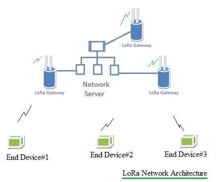
The LoRaWAN devices are categorized into three main classes: class-A, class-B, and class-C, based on their application needs. The figure below depicts the network topology of a LoRaWAN system, which uses a “star of stars” topology.
The figure above depicts the LoRaWAN network architecture with its elements. Let’s understand the functions of each element:
End Device
This LoRaWAN device functions as a sensor or actuator. It connects wirelessly with the LoRaWAN network through a LoRaWAN gateway. All the payloads of an application layer are routed to its connected application server in the cloud.
LoRaWAN Gateway Device
It forwards received radio packets to the network server through the backbone. It receives radio packets from the air and forwards them to the network server without any processing. Similarly, it does not alter payloads coming from the network server to be uploaded over the air. It performs the necessary RF conversion.
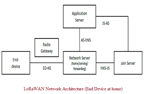
Network Server (NS)
The NS performs many functions, including end device address checking, frame authentication, acknowledgements, and data rate adaptation. It interfaces with the application server and Join server. NS has three roles (Home, Serving, Forwarding) based on roaming situation and type of roaming.
Join Server (JS)
It manages the OTA activation process of end devices. Several JSs are connected to a single NS. Moreover, a JS may connect to several NSs.
Application Server (AS)
The Application Server handles all the application layer payloads of the associated LoRaWAN End-Devices. It provides the application-level service to the end-user.
LoRaWAN Network Interfaces
The following table mentions LoRaWAN network interfaces used between its network elements.
| LoRaWAN Interface | Description |
|---|---|
| hNS-JS | Used for activation procedure between the join server and network server. |
| vNS-JS | Used for roaming activation procedure to retrieve the NetID of hNS associated with the End device. |
| ED-NS | LoRaWAN MAC layer signaling. Payload delivery between the End device and Network server. |
| AS-hNS | Delivery of application payload and associated meta-data between the AS (Application Server) and NS (Network Server). |
| hNS-sNS | Roaming signaling and Payload delivery between the home network server (hNS) and Serving NS (sNS). |
| sNS-fNS | Roaming signaling and Payload delivery between the serving network server (sNS) and forwarding NS (fNS). |
| AS-JS | To deliver the application session key from the Join server (JS) to the Application server (AS). |
Reference: LoRaWAN Backend Interfaces document V1.0, Visit www.lora-alliance.org to download it.
Conclusion
The LoRaWAN architecture provides a robust and scalable framework for deploying IoT networks, enabling seamless data transmission across different components. This architecture makes LoRaWAN a powerful choice for diverse applications, from smart cities to industrial automation. It helps developers in effective management of data handling, reduces latency, and ensures secure communication within IoT deployments.
Advertisement


