LTE Testing: UE Test and Measurement, EVM, Sensitivity
Advertisement
This page covers LTE testing as per LTE UE compliant to 3GPP conformance test. It covers LTE UE Test and Measurement viz. EVM, receiver sensitivity, maximum power reduction, IQ, spectrum mask, ACLR, RSRP etc. This LTE Test and measurement tutorial covers LTE baseband and RF measurements useful for UE conformance testing.
Following basic LTE UE transmitter and Receiver tests are done during this LTE UE testing.
LTE UE Transmitter
Following LTE measurements are carried on UE transmitter part as LTE testing.
Maximum Output Power
To verify that the error of the UE maximum output power does not exceed the range prescribed by the specified nominal maximum output power and tolerance. Output power exceeding certain value will interfere with nearby channels and wireless systems. At the same time power should not be too low as smaller transmit power will cover lesser distance.
For E-UTRA frequency bands in LTE from 1 to 14 and 33 to 40 and class 3 specification the limit is 23dBm with tolerance of +/-2 dB.
Maximum Power Reduction (MPR)
For maximum output power allowed MPR due to higher modulation and transmit bandwidth configuration is as mentioned below. For QPSK modulation, 10MHz BW and RB > 12 , MPR is <=1dB.
Output Power Dynamics (power control)
Power control is used to limit the interference level and compensate the channel fading. To verify the ability of the UE transmitter to set its initial output power to a specific value at the start of a contiguous transmission or non-contiguous transmission with a long transmission gap, i.e. transmission gap is larger than [x] ms.
Under normal conditions, tolerance limit is +/-10.5dB. Under extreme conditions, tolerance limit is +/-13.5dB.
Min. Output Power
The test purpose here is to check LTE UE transmit minimum power as specified without any problem in the system performance. The minimum output power is defined as mean power in 1 ms subframe.
LTE UE should be tested with min. power value of -39dBm for all the supported channel bandwidths which include 1.4 MHz,3 MHz,5 MHz,10 MHz,15 MHz and 20MHz.
Frequency Error
The UE modulated carrier frequency shall be accurate to within +/- 0.1 PPM observed over a period of one time slot (0.5ms) compared to the carrier frequency received from the E-UTRA Node B.
Error Vector Magnitude (EVM)
This is modulation quality test of the LTE transmitter. This test is used to ensure compliance with requirements for EVM. The purpose of this test is to exercise the UE transmitter to verify its modulation quality in terms of Error Vector Magnitude.
Before this measurements both frequency offset and IQ offset is corrected. For PUSCH LTE channel, EVM for QPSK modulation should be 17.5% and EVM for 16QAM modulation should be 12.5%. This limit is with UE output power of >= -40dBm under normal operating conditions and in a slot duration.
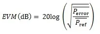
EVM is measured in dB as shown in the equation above,
Where is the RMS power of the error vector and is the reference constellation average power.
IQ Component
I/Q origin offset is an interference caused by crosstalk or DC offset. It is an interference of approximately constant amplitude and independent of the amplitude of the wanted signal. I/Q origin offset interferes with the center sub carriers of the UE under test.The measurement interval is defined over one slot in the time domain.
This test help to verify UE transmitter’s modulation quality in terms of IQ origin offset. The relative carrier leakage power (IQ origin offset power) shall not exceed following:
- IQ origin offset at Max Pout -25 dBc at full RB allocation
- IQ origin offset at -40dBm -10 dBc at full RB
Spectrum Emission Mask
Out of band emissions are unwanted emissions immediately outside the nominal channel resulting from the modulation process and non-linearity in the transmitter but excluding spurious emissions. This test is specified in terms of a Spectrum Emission Mask and Adjacent Channel Leakage power Ratio. Measure the spectrum emission mask at maximum output power.
Adjacent Channel Leakage Power Ratio (ACLR)
The purpose of this test is to verify that UE transmitter does not cause unacceptable interference to adjacent channels in terms of Adjacent Channel Leakage power Ratio (ACLR). ACLR is the ratio of the power on assigned channel to power on the adjacent channel frequency.
- E-UTRA ACLR1 limit is about -30 dBc
- UTRA ACLR1 limit is about -33 dBc
- UTRA ACLR2 limit is about -36 dBc
LTE UE Receiver
Following LTE measurements are carried on UE receiver part as LTE testing.
LTE Receiver Sensitivity Level (RX EVM)
The receiver sensitivity shall be measured for primary and diversity receiver respectively. The EVM test with the lower power level is to verify that the ME fulfills requirements on receiver sensitivity.
LTE UE Test Requirements (EVM)
- Transmitter shall be enabled at maximum output power for all tests.
- Number of used samples must be enough to guarantee a measurement accuracy of <=0.1 dB.
For LTE Band 13 with bandwidth of 5 MHz, EVM should be 0.8dB at input level -97 dBm,QPSK modulation in high channel condition. EVM should be -16.2dB at input level -50 dBm,64QAM modulation in high channel condition.
Reference Signal Received Power (RSRP)
The purpose is to test the RSRP from the ME with LTE mode of operation. The power sweep will test that all analog gain settings are functional and the frequency sweep will test that frequency response is sufficiently flat.
- power sweep: RSRP Accuracy of -6 to +6dB with Mid-channel conditions at 10 MHz(bandwidth) and input power of -90 to -70 dBm.
- Frequency sweep: RSRP Accuracy of -6 to +6 dB at 5 MHz bandwidth and input power of -70dBm.