Asynchronous Transfer Mode (ATM) Tutorial
Advertisement
Asynchronous Transfer Mode (ATM) is a high-speed networking technology designed for efficient data transfer across diverse media types, such as voice, video, and data. ATM operates on a cell-based architecture, where data is segmented into fixed-size cells for fast switching and transmission.
In this tutorial, we will cover the basics of Asynchronous Transfer Mode (ATM) in computer networks, including the ATM architecture diagram, cell size, format & types, protocol layers, addressing formats, and ATM services.
In the year 1980, ITU-T initiated efforts to develop a network that could transport voice, video, and data simultaneously from source to destination. As a result, B-ISDN (Broadband Integrated Services Digital Network) was developed. The B-ISDN combines telephony networks, data networks, and cable TV networks into a single network. ATM, as well as SONET/SDH, are behind the success of B-ISDN.
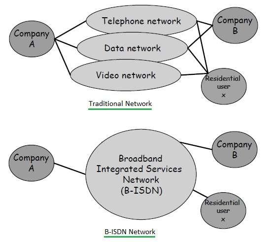
Figure-1 : Traditional network vs B-ISDN network
The same is shown in Figure-1. Unlike Synchronous Transfer Mode where each source gets periodic assignment of bandwidth similar to TDM, the source in ATM packetizes data into smaller fixed-size cells, and cells are sent only if there is data to be transmitted. In ATM, each of the cells will have its own header as described later.
ATM Cell Format and Cell Size
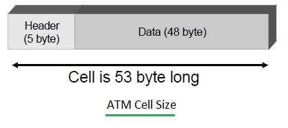
Figure-2 : ATM cell size and ATM format
Following are the silent features of ATM (Asynchronous Transfer Mode):
- ATM uses Virtual Circuit Packet Switching and reserves capacity for the virtual circuit.
- Packets are known as cells in ATM. The smaller packets are good for voice as well as video transmissions. One ATM cell consists of a header (5 bytes) and data payload (48 bytes).
- It allows multiple logical connections to be multiplexed over a single physical interface.
- It is a connection-oriented technology.
- As mentioned, it provides dynamic allocation of bandwidth for efficient traffic management.
- Supports minimum flow control and error control capabilities.
- Supports LAN, CAN, and WAN.
- ATM can be deployed in private, public, or hybrid networks.
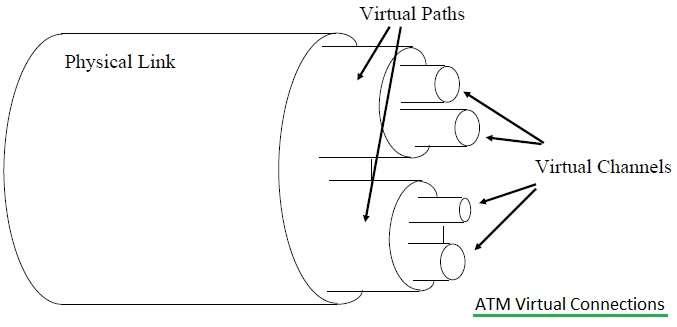
Figure-3 : ATM virtual connections
-
In ATM (Asynchronous Transfer Mode), logical connections are known as virtual channel connections or VCCs. The VCC is similar to a virtual circuit (VC) in a packet-switched network and is the unit of switching used in an ATM network.
-
Initially, a VCC is established between end users in the network.
-
After the VCC connection is established, variable rate and fixed-size cells are exchanged.
-
Here, VPC (Virtual Path Connection) is a combination of VCCs having the same endpoints or destinations. Hence, all the ATM cells traveling through VCCs in one common VPC are switched together.
-
A virtual path is identified by VPI, and a Virtual Channel is identified by VCI as mentioned below.
- VPI (Virtual Path Identifier) identifies a virtual path (8/12 bits in size).
- VCI (Virtual Channel Identifier) identifies a virtual channel in a virtual path (16 bits).
ATM Architecture Diagram with Network Interfaces
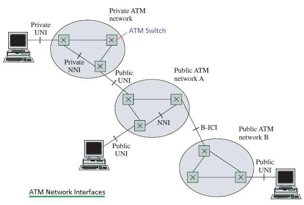
Figure-4 : ATM network architecture
- Figure-2 depicts the ATM network architecture diagram with ATM network interfaces.
- There are two types of Virtual connections supported by ATM network viz. PVCs and SVCs.
- PVCs are referred to as Permanent Virtual Connections. They are similar to leased lines used between users, and they are set up by the operator.
- SVCs are referred to as Switched Virtual Connections. They are set up and torn down based on end-user demand.
- The ATM network interfaces include UNI (User-Network Interface), NNI (Network-Network Interface), and B-ICI (Broadband Intercarrier Interface). A user interacts with the network using the UNI interface to establish an SVC connection. The ATM switches interact using the NNI interface in order to exchange information. ATM switches belonging to another public networks will communicate using B-ICI interface.
ATM Cell Types: UNI Cell vs NNI Cell
As mentioned earlier, an ATM cell is composed of a header and payload part. The total ATM cell size is about 53 bytes including the header and payload. The header is of size equal to 5 bytes or octets, and the payload, which carries information from upper layers, is of size equal to 48 bytes. The header of ATM (Asynchronous Transfer Mode) cell varies in UNI interface and NNI interface. The same has been shown in the figure below. Let us understand the difference between the UNI cell header and the NNI cell header. As shown, the GFC field is used only in UNI cells. At NNI, the GFC byte is used to incorporate additional VPI. The following table mentions ATM cell types UNI cell and NNI cell.
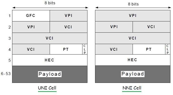
Figure-5 : ATM cell types
| UNI Cell Header field | Size | Description |
|---|---|---|
| GFC | 4 bits | Generic Flow Control |
| VPI | 8 bits | Virtual Path Identifier, It is a routing field for the network. |
| VCI | 16 bits | Virtual Channel Identifier, It is used for routing to and from end user. It acts as SAP(Service Access Point). |
| PT | 3 bits | Payload Type |
| CLP | 1 bit | Cell Loss Priority, value of 0 indicates that cell should not be discarded. Value of 1 indicates that cell can be discarded. |
| HEC | 8 bits | Header Error Control, It is used to correct single bit errors in the header. It is also used to detect double bit errors. |
Table-1 : UNI Cell Header fields
| NNI Cell Header field | Size | Description |
|---|---|---|
| VPI | 8/12 bits | Virtual Path Identifier |
| VCI | 16 bits | Virtual Channel Identifier |
| PT | 3 bits | Payload Type |
| CLP | 1 bit | Cell Loss Priority |
| HEC | 8 bits | Header Error Control |
Table-2 : NNI Cell Header fields
ATM Addressing Formats: DCC, ICD, E.164
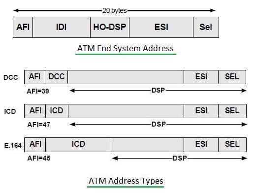
Figure-6 : ATM addressing formats
All ATM (Asynchronous Transfer Mode) addresses are 20 bytes in size. Source and destination addresses are used while establishing a connection. There are three types of ATM addressing formats viz. NSAP (Network Service Access Point), DCC, and ICD.
- ATM endpoints use NSAP format. ISDN telephone numbers use the format E.164.
- DCC (Data Country Code) format is used for public networks.
- ICD (International Code Designator) format is used for private networks.
The following table describes fields used in ATM addressing.
| Field | Size | Description |
|---|---|---|
| AFI | 1 byte | Authority and Format Identifier, tells which addressing scheme is used. |
| IDI | 2-8 bytes | Initial Domain Identifier, Identifies a domain within scope of addressing authority. |
| HO-DSP | 4-10 bytes | High Order bits of domain-specific part, same as the network prefix of an IP address |
| ESI | 6 bytes | End System Identifier, Same as host number of IP address |
| SEL | 1 byte | Selector, for end-system use only |
Table-3 : ATM addressing fields
ATM Protocol Stack Layers
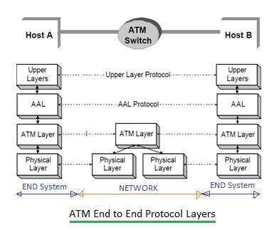
Figure-7 : ATM Protocol Stack
The ATM protocol stack consists of three main layers viz. AAL Layer, ATM layer, and physical layer. Above the AAL layer, upper layers reside. Following are the functions of each.
- AAL layer does encapsulation of user-level data. AAL layer breaks the upper layer data at the sender side into small-size ATM cells and reassembles the cells at the receiver side.
- ATM layer takes care of the transport of 53-byte ATM cells created by the AAL layer across the ATM network. It does multiplexing of multiple logical channels on one single physical channel. It provides different services for ATM cells.
- The ATM physical layer does encoding (at the transmit end) and decoding (at the receive end) of bits based on the physical medium used for the transportation of ATM cells.
ATM Services: CBR, rt-VBR, nrt-VBR, ABR, UBR, GFR
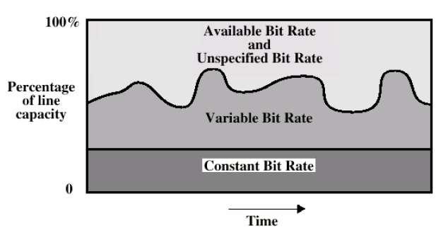
Figure-8 : ATM services
The ATM layer provides the following different kinds of ATM services for ATM cells as per requirement in different applications. The table mentions the same.
| ATM Service Type | Description |
|---|---|
| CBR-Constant Bit Rate | • guarantees a fixed capacity, similar to circuit switching • guarantees a maximum delay for cells |
| VBR-Variable Bit Rate | • Supports both real-time and non-real-time applications • guarantees an average throughput and maximum delay |
| ABR-Available Bit Rate | • guarantees “fairness” with respect to other traffic |
| UBR-Unspecified Bit Rate | • service is on a “best effort” basis |
| GFR-Guarantees Frame Rate | • Throughput guarantee for multiple cell frames |
Table-4 : ATM service types
Conclusion
ATM technology, with its unique cell-based approach and layered architecture, revolutionized data transmission by offering high-speed, reliable communication. Understanding its architecture, cell structure, and protocols is essential for anyone working with telecommunications or network infrastructure. This tutorial is very useful for beginners who would like to understand and implement Asynchronous Transfer Mode (ATM) technology in various computer network scenarios.
Advertisement
 RF
RF


