ATM Switch in Networking: Functions and Working
Advertisement
In networking, an ATM switch plays a pivotal role in managing data transmission within Asynchronous Transfer Mode (ATM) networks. ATM is a connection-oriented protocol designed to handle diverse types of traffic, including voice, video, and data, in high-speed environments. The ATM switch is responsible for forwarding fixed-size cells based on Virtual Path Identifier (VPI) and Virtual Channel Identifier (VCI) mappings. This technology ensures efficient bandwidth utilization, traffic management, and quality of service (QoS) across the network.
In this article, we will explore the functions of ATM switches, their role in cell switching, how they work, and how they handle key operations like VP/VC mapping and congestion control. ATM Switch differs from a conventional switch due to its high-speed interface, typically ranging from 50 Mbps to 2.4 Gbps. The switch is designed to handle broadband applications and prioritize certain types of traffic through the ATM network.
EXAMPLE: Voice traffic cannot tolerate much delay and therefore needs to be handled with high priority compared to email.
How ATM Switches Work
The switch which works on packet switching technology to allow voice, data, image and video traffic over high speed single access circuit is known as ATM Switch. It divides the information as mentioned into equal size cells of size equal to 48 bytes and adds header (of size 5 bytes) before transmission.
Here, 48 bytes contain the information, and 5 bytes contain control information.
ATM (Asynchronous Transfer Mode) Switch works on same size cells and hence cell delay is manageable and predictable. ATM switches are responsible for forwarding these cells from one part of the network to another. They operate at both the data link layer (Layer 2) and the network layer (Layer 3) of the OSI model. The switch performs functions based on the Virtual Path Identifier (VPI) and Virtual Channel Identifier (VCI) found in the header of ATM cells. ATM network composed of more than one ATM switches between source and destination systems. The switch consists of input ports and output ports. These ports are interconnected with users, other ATM switches and other network elements.
- ATM (Asynchronous Transfer Mode) Switch functions are categorized into three planes viz. user plane, control plane, management plane. ATM cells are divided into data cells and control cells.
- USER PLANE: ATM Switch relays data cells from input to output ports. The switch operates on cell headers and not on payload. The payload is carried transparently through the switch. When a cell arrives at an input port, the switch checks the VPI/VCI and routes cells accordingly to the output ports.
- CONTROL PLANE: Information in the payload part of control cells is not transparent here. It is verified and checked by the ATM switch, and based on the same, appropriate actions are taken by it. The control plane takes care of the establishment and control of VP and VC connections.
- MANAGEMENT PLANE: Takes care of monitoring and control of the ATM network.
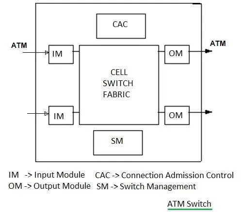
The figure-1 depicts typical modules in an ATM switch. It’s composed of Input modules, output modules, CAC (connection admission control), switch management and cell switch fabric.
Functions of ATM Switch
- Cell Switching: The primary function of an ATM switch is to forward incoming ATM cells to the correct output port based on the VPI/VCI information in the header. It uses a switching table to map the incoming cells’ virtual circuits to the correct outgoing paths.
- Traffic Management: ATM switches handle different types of traffic (e.g., Constant Bit Rate (CBR), Variable Bit Rate (VBR), and Available Bit Rate (ABR)) and manage quality of service (QoS) requirements for each type. This ensures reliable performance for time-sensitive applications such as video conferencing.
- Cell Multiplexing: The ATM switch can multiplex multiple virtual circuits over a single physical link. This enables efficient use of network bandwidth by allowing multiple data streams to share the same transmission medium.
- Congestion Control: To prevent network congestion, ATM switches implement flow control mechanisms. They monitor the network’s load and buffer traffic during congestion, ensuring that no data is lost and minimizing packet delays.
- Routing and Addressing: The ATM switch uses the VPI/VCI fields in the ATM cell header for addressing and routing purposes. It looks up the switching table to determine the path each cell should take through the network, ensuring that it reaches its correct destination.
- Cell Buffering and Queueing: ATM switches provide buffering and queueing mechanisms to handle temporary traffic bursts. If the switch’s output port is busy, the cells are queued in memory buffers until the output is available, ensuring smooth data transmission.
- Error Handling: Although ATM switches do not provide extensive error checking (relying on upper layers for this), they do offer mechanisms to detect and discard corrupted cells, maintaining data integrity in the network.
VP/VC ATM Switch
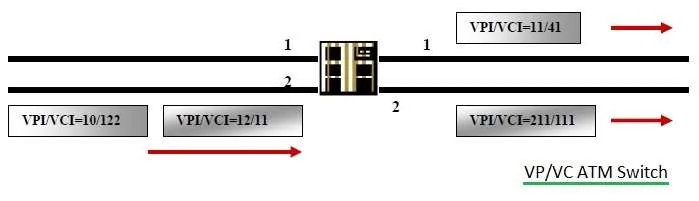
ATM switch uses two types of switches viz. VP switch and VP-VC switch. Typically, switches connected to users are VPI/VCI switches while all intermediate switches are only VPI switches. All VPIs and VCIs field have local significance across a particular link. These values are re-arranged or re-mapped as required at the ATM (Asynchronous Transfer Mode) switch.
| Incoming VPI | Incoming VCI | Outgoing VPI | Outgoing VCI | Interface |
|---|---|---|---|---|
| 10 | 122 | 11 | 41 | 1 |
| 121 | 213 | 10 | 158 | 1 |
| 12 | 11 | 211 | 111 | 2 |
| 11 | 151 | 321 | 210 | 2 |
- As shown in figure-2, When cell arrives at the input of ATM switch, it looks up connection value in local table referred as translation table to determine appropriate outgoing port for the connection.
- It also assigns new VPI/VCI value of the connection on the same outgoing link.
- The switch re-transmits cell on the outgoing link with appropriate identifier.
VP ATM Switch
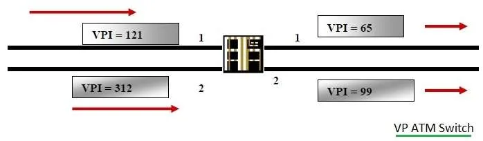
VP switch routes cells based on VPI only. Here VPI values do not change but VCI values remain the same during switching. It uses a translation table for switching.
| Incoming VPI | Outgoing VPI | Interface |
|---|---|---|
| 22 | 65 | 1 |
| 121 | 99 | 2 |
| 312 | 201 | 1 |
| 11 | 21 | 2 |
Conclusion
In summary, an ATM switch plays a vital role in forwarding ATM cells across a network efficiently, ensuring high-speed data transmission, managing traffic, and maintaining QoS.