 RF
RF8085 Microprocessor Programming Tutorial
Advertisement
This page provides a tutorial on 8085 microprocessor programming, covering the 8085 instruction set and addressing modes, including immediate, register, direct, and indirect addressing. It explains instructions of various lengths (1-byte, 2-byte, and 3-byte) and provides example assembly programs.
The 8085 microprocessor consists of the following key components:
- Control Unit: Generates signals within the microprocessor to execute decoded instructions. Manages data movement for ALU operations.
- ALU Unit: Performs arithmetic and logical operations like ADD, Subtract, AND, OR, etc. Uses data from memory, registers, and the Accumulator. Stores the final result in the Accumulator.
- Registers: Six general-purpose 8-bit registers (B, C, D, E, H, L) for data storage. Can be combined as BC, DE, and HL to store 16-bit data. Other important registers include the Accumulator, Program Counter (PC), Stack Pointer (SP), and a flag register. Data can be stored in these registers using data copy instructions.
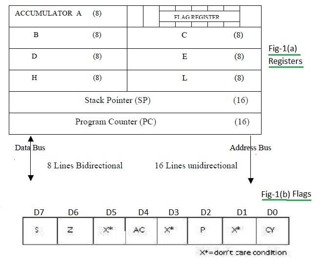
Figure 1 depicts these registers.
The Accumulator is an 8-bit register used to store data, perform mathematical operations, and hold the final result. It’s designated as ‘A’. The ALU includes five flip-flops used as flags, which are set or reset based on conditions during mathematical operations. These flags are S (Sign), Z (Zero), AC (Auxiliary Carry), P (Parity), and CY (Carry), arranged from MSB positions.
EXAMPLE: After adding two numbers, if the sum exceeds 8 bits, the CY flag is set to ‘1’. Each flag has significance in the 8085 processor.
| Item | Description |
|---|---|
| Registers | 8-bit general-purpose registers (B, C, D, E, H, L). |
| Accumulator | 8-bit register used to store the result and intermediate operations of mathematical operations. |
| Flags | Five flags that are set and reset based on arithmetic and logical conditions. |
| Program Counter (PC) | 16-bit register that sequences instruction execution. Used as a memory pointer, holding the address of the next byte to be fetched. Incremented by 1 after each byte fetch to point to the next location. |
| Stack Pointer (SP) | 16-bit register that points to a memory location (stack) in R/W memory. The beginning of the stack is defined by loading a 16-bit address into the SP. |
8085 Addressing Modes
- Immediate Addressing: Loads immediate data directly into the destination. The data is specified within the instruction itself.
- EXAMPLE:
MVI R, Data
- EXAMPLE:
- Register Addressing: Data is stored in registers, and operations are performed using these registers in the instructions.
- EXAMPLE:
MOV Rd, Rs(Rd = destination register, Rs = source register)
- EXAMPLE:
- Direct Addressing: Used to accept data from external devices and store it in the Accumulator (input). Also used to send data from the Accumulator to external devices (output).
- EXAMPLE (Input):
IN 00H - EXAMPLE (Output):
OUT 01H
- EXAMPLE (Input):
- Indirect Addressing: The effective address is calculated by the microprocessor. This method requires multiple memory accesses to retrieve the data to be loaded into the register.
Instruction Set Classification
An instruction is a binary pattern within the microprocessor that triggers a specific function. The complete set of instructions is known as the “Instruction Set”. The 8085 instructions are categorized as follows:
- Data Transfer Operations (Copy): Used to copy data from a source location to a destination location. Types include:
- Between Registers
- Specific data byte to a register or memory location
- Between a memory location and a register
- Between an I/O device and the accumulator
- Arithmetic Operations: Instructions for addition, subtraction, increment, and decrement.
- Logical Operations: Instructions for logical operations on the Accumulator’s contents, such as AND, EX-OR, Rotate, Compare, Complement, etc.
- Branching Operations: Instructions to alter program execution sequence conditionally or unconditionally (e.g., Jump, Call, Return).
- Machine Control Operations: Instructions to control machine functions (e.g., Halt, Interrupt, Do nothing).
8085 Instruction Format
8085 instructions are classified into three groups based on size:
- One-word (1-byte) instructions
- Two-word (2-byte) instructions
- Three-word (3-byte) instructions
An Instruction is a command to the microprocessor to perform a given task on specified data. Each instruction has two parts: the operation code (opcode) specifying the task and the operand, which is the data to be operated upon. The operand can be 8-bit data, 16-bit data, an internal register, a memory location, or an 8-bit/16-bit address.
| Task | Opcode | Operand | Binary Code | Hex Code |
|---|---|---|---|---|
| Add the contents of register B to contents of accumulator | ADD B | 1000 0000 | 80H | |
| Copy contents of accumulator in register C | MOV C, A | 01001111 | 4FH |
| Task | Opcode | Operand | Binary Code | Hex Code |
|---|---|---|---|---|
| Load 8 bit data byte in the accumulator | MVI A, data | data | 0011 1110, data | 3E, data |
If the data byte 32H needs to be moved into the accumulator:
MVI A, 32H
Hex code: 3E 32H
| Task | Opcode | Operand | Binary Code | Hex Code |
|---|---|---|---|---|
| Transfer the program sequence to memory location 2085H. | JMP 2085H | 11000011 10000101 00100000 | C3 85 20 |
Sample 8085 Assembly Programs
Example 1: Write an assembly program to add two numbers.
MVI D, 8CH   ; Load 8CH into register D
MVI C, 6EH   ; Load 6EH into register C
MOV A, C     ; Move the content of C to Accumulator
ADD D        ; Add content of D with Accumulator , result in A
OUT PORT1    ; Output the result to PORT1
HLT          ; Halt the program
Example 2: Write an assembly program to multiply a number by 8 (Multiply by 2 is equivalent to shifting).
MVI A, 40H   ; Load 40H into Accumulator
RLC          ; Rotate Accumulator left (Multiply by 2)
RLC          ; Rotate Accumulator left (Multiply by 2)
RLC          ; Rotate Accumulator left (Multiply by 2)
OUT PORT1    ; Output the result to PORT1
HLT          ; Halt the program
Example 3: Write an assembly program to find the greatest between two numbers.
MVI B, 30H    ; Load 30H into register B
MVI C, 40H    ; Load 40H into register C
MOV A, B      ; Move the content of B to Accumulator
CMP C         ; Compare Accumulator with C
JZ EQU        ; Jump to EQU if Zero flag is set (A = C)
JC GRT        ; Jump to GRT if Carry flag is set (A < C)
OUT PORT1     ; Output the result to PORT1
HLT           ; Halt the program

EQU:
MVI A, 01H    ; Load 01H into Accumulator (Equal)
OUT PORT1     ; Output the result to PORT1
HLT           ; Halt the program

GRT:
MOV A, C      ; Move the content of C to Accumulator (C is greater)
OUT PORT1     ; Output the result to PORT1
HLT           ; Halt the program
Advertisement


