5G NR Network Interfaces: Xn, NG, E1, F1, F2 Explained
Advertisement
This page provides an overview of the various interfaces used within the 5G NR (New Radio) network architecture. We’ll explore the Xn, NG, E1, F1, and F2 interfaces, highlighting their functions and locations within the 5G RAN and 5GC. Our information is based on the 3GPP TS 38.300 specification.
The 5G NR network is composed of the NG-RAN (Next Generation Radio Access Network) and the 5GC (5G Core Network). The NG-RAN consists of gNBs (5G base stations) and ng-eNBs (LTE base stations).
-
The Xn interface exists between these base stations: gNB-gNB, gNB-ng-eNB, and ng-eNB-ng-eNB. It’s the network interface connecting NG-RAN nodes. Xn-U refers to the Xn User Plane interface, while Xn-C is the Xn Control Plane interface.
-
The NG interface connects the 5GC to these base stations (gNB & ng-eNB).
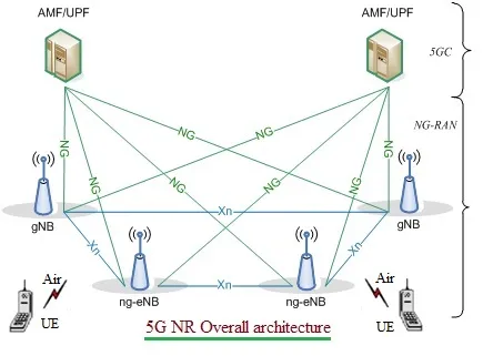
5G NR Overall architecture
Here’s a breakdown of the interfaces and nodes as depicted in the figures:
- NG-C: Control plane interface between NG-RAN and 5GC.
- NG-U: User plane interface between NG-RAN and 5GC.
- gNB: A node providing NR user plane and control plane protocol terminations towards the UE (User Equipment). It connects to the 5GC via the NG interface. Specifically, the 5G NR gNB is connected to the AMF (Access and Mobility Management Function) and UPF (User Plane Function) within the 5GC. The protocol layers are organized into three units: RRH (Remote Radio Head), DU (Distributed Unit), and CU (Central Unit).
- ng-eNB: A node providing E-UTRA (Evolved Universal Terrestrial Radio Access) user plane and control plane protocol terminations towards the UE, connected to the 5GC via the NG interface.
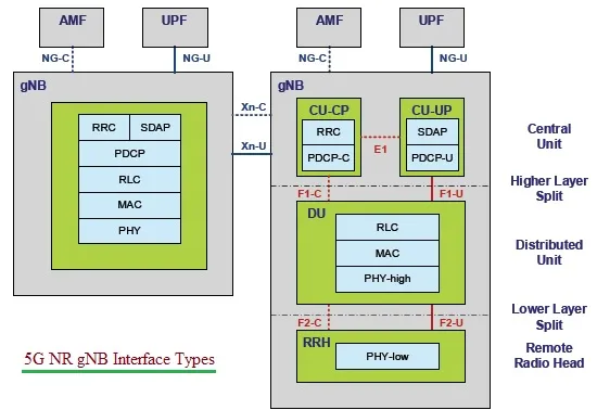
5G NR gNB interfaces
The figure above illustrates the control and user plane interfaces connecting to the 5G Core Network (5GC).
Locations and Functions of 5G NR Interfaces
Let’s delve deeper into the specific locations and functions of each interface.
5G NR Xn Interface
- Location: Between NG-RAN Nodes (gNB & ng-eNB).
- Control Plane Functions:
- Interface management and error handling (e.g., setup, reset, removal, configuration update)
- Connected mode mobility management (handover procedures, sequence number status transfer, UE context retrieval)
- Support of RAN paging
- Dual connectivity functions (secondary node addition, reconfiguration, modification, release, etc.)
- User Plane Functions:
- Data Forwarding
- Flow Control
- References: TS 38.420 to TS 38.424
5G NR NG Interface
- Location: Between 5G RAN and 5G Core Network. The control and user planes are separated with NG-C and NG-U, respectively. It is similar to LTE interfaces viz. S1-C and S1-U respectively.
- Functions/Objectives:
- Supports the exchange of signaling information between NG-RAN and 5GC.
- Defines the interconnection of NG-RAN nodes with AMFs supplied by different manufacturers.
- Specifies the separation of NG interface Radio Network functionality and Transport Network functionality to facilitate the introduction of future technologies.
- Capabilities:
- Procedures to establish, maintain, and release the NG-RAN part of PDU sessions.
- Procedures to perform intra-RAT (Radio Access Technology) handover and inter-RAT handover.
- Separation of each UE on the protocol level for user-specific signaling management.
- Transfer of NAS (Non-Access Stratum) signaling messages between UE and AMF.
- Mechanisms for resource reservation for packet data streams.
- References: TS 38.410 to TS 38.414
5G NR E1 Interface
- Location: From a logical perspective, the E1 interface is a point-to-point interface between a gNB-CU-CP (Central Unit - Control Plane) and a gNB-CU-UP (Central Unit - User Plane).
- Functions:
- Supports the exchange of signaling information between the endpoints.
- Separates the Radio Network Layer and Transport Network Layer.
- Enables the exchange of UE-associated information and non-UE-associated information.
- References: TS 38.460 to TS 38.463
5G NR F1 Interface
- Location: Between gNB-CU and gNB-DU (Distributed Unit). Separated into F1-C and F1-U based on control plane and user plane functionalities.
- Functions:
- Defines the interconnection of a gNB-CU and a gNB-DU supplied by different manufacturers.
- Supports control plane and user plane separation.
- Separates the Radio Network Layer and Transport Network Layer.
- Enables the exchange of UE-associated information and non-UE-associated information.
- References: TS 38.470 to TS 38.475
5G NR F2 Interface
This interface resides between the lower and upper parts of the 5G NR physical layer. Like the other interfaces, it’s also separated into F2-C and F2-U based on control plane and user plane functionalities.
Conclusion
The 5G NR network architecture introduces several key interfaces such as Xn, Ng, E1, F1, and F2 , to enable seamless communication between network components. The Xn interface connects gNodeBs (gNBs) for inter-cell coordination, while the Ng interface links the gNB to the core network for user and control plane traffic. The E1 interface facilitates communication between gNB’s Centralized Unit Control Plane (CU-CP) and Centralized Unit User Plane (CU-UP), ensuring efficient network management. Meanwhile, the F1 interface connects the CU and Distributed Unit (DU), allowing flexible RAN deployments, and the F2 interface supports communication between multiple DUs under the same CU. These interfaces collectively enhance network flexibility, scalability, and performance, making 5G NR networks more efficient and capable of handling next-generation connectivity demands.