Microcontrollers: Architecture, Pins, and Functions
Advertisement
A microcontroller is essentially a small computer on a single integrated circuit (IC) designed to perform a specific task or application.
It’s comprised of key components like:
- CPU (Microprocessor)
- RAM (Random Access Memory)
- ROM (Read-Only Memory)
- I/O Ports (Input/Output)
- Timers
- Counters

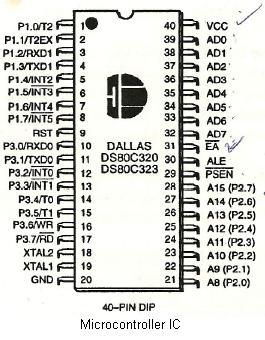
Let’s explore some of the essential microcontroller pins and their functions:
Essential Microcontroller Pins and their Functions
ALE (Address Latch Enable)
The 8051, based on Harvard architecture, utilizes separate program and data memory connected externally. This external memory is accessed using 16 lines, where 8 of these lines act as both data lines and the lower-order 8 lines of the 16-bit external address.
To enable these 8 lines to function first as address lines and then as data lines, an 8-bit external latch is employed. The ALE output pulse serves as the control signal, latching the low byte of the address during external memory accesses. ALE’s frequency is about 1/6 of the oscillator frequency, and it is utilized for external timing/clocking purposes. It also functions as the PROG pin during EPROM programming.
PSEN (Program Store Enable)
This is the read strobe for the interfaced external Program Memory. It activates twice each machine cycle when the device is executing from the external program memory but remains inactive when executing from internal program memory.
EA/VPP (External Access/Voltage Programming Pin)
When this pin is high, the microcontroller’s CPU executes from internal program memory. Setting EA to low forces the CPU to execute from external memory. The EA pin receives supply voltage during EPROM programming.
XTAL1 & XTAL2
These pins facilitate the connection of an external clock frequency, typically within the 4MHz to 30MHz range. XTAL1 connects to the input of the inverting-oscillator-amplifier, while XTAL2 connects to the output.
There are two common methods for providing the external clock frequency:
- Using a quartz crystal oscillator
- Using a TTL Oscillator
Ports
As illustrated in the figure, the Dallas microcontroller 80c320 features four ports: Port 0, Port 1, Port 2, and Port 3.
Port 0
Port 0 is an 8-bit open-drain bi-directional port. During external memory accesses, Port 0 also serves as the multiplexed low-order address and data bus.
Port 1
This port is an 8-bit bi-directional I/O port. Pins with a ‘1’ written to them are pulled high by internal pull-up resistors, allowing them to function as inputs.
Port 2
Port 2 is another 8-bit bi-directional I/O port. It emits the high-order address byte during external memory accesses that utilize 16-bit addresses.
Port 3
Port 3, also an 8-bit bi-directional I/O port, provides access to various special features of the 80C51 Family.
RST (Reset)
This input pin is active high (normally low). Applying a high pulse to RST resets all registers and terminates all operations. The pulse must remain high for at least two machine cycles for the reset to function correctly.
There are two primary methods to reset the 80C51:
- Power-on reset circuit
- Power-on reset with debounce
VCC
Supply Voltage - Typically +5V
Vss
Circuit ground potential
Advertisement
 RF
RF


