 RF
RFWhat is Passive Intermodulation Distortion (PIM)
Advertisement
Passive Intermodulation (PIM) distortion is an unwanted signal interference phenomenon caused by nonlinearities in passive RF components such as connectors, antennas and cables. PIM can degrade network performance, reduce signal quality and impact wireless coverage, making it a critical concern in cellular communication systems.
Passive Intermodulation (PIM) distortion is a critical challenge in modern RF systems, causing interference and degrading wireless performance. PIM arises from non linearities in passive components like connectors, cables or antennas. Understanding its causes and effects is vital for designing reliable communication networks. Effective PIM mitigation techniques, such as proper installation, component selection and regular maintenance, help reduce signal interference. This guide explores PIM in detail and provides practical solutions to address it.
What is Intermodulation Distortion (IMD)?
When two or more signals are mixed in a non-linear component, whether active or passive, other signals are generated as a result of the product of these original signals. This condition is referred to as IMD or Intermodulation Distortion. This will occur in amplifiers operating in a non-linear mode. Hence, it is desirable to operate the amplifier within a certain limit set by the standard. Due to this, the amplifier operates below its operating point and hence works in a linear region without much distortion.
Check below for other methods to minimize or mitigate IMD. The frequencies which are generated due to intermodulation can be the sum or difference of various IMD products. Based on the IMD products that are generated, there will be second order, third order, fourth order, and so on.
Let us assume for the sake of understanding that there are two frequencies and which exist at the input of a non-linear operating amplifier. This will generate frequencies as shown in Figure 1.
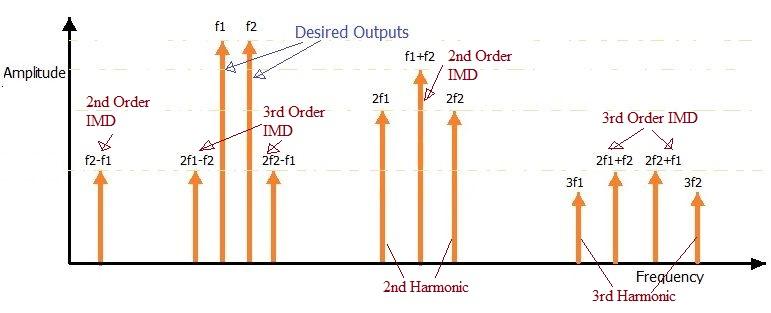
Figure-1: IMD Products
As shown in the figure, there are many products, but the major consequences will be due to and as they exist near to desired frequencies (, ) in the frequency spectrum.
The table below mentions various intermodulation classes (with different orders and number of channels) and their outputs.
| Intermodulation order /channels | IMD products |
|---|---|
| 2nd Order 2 channels(, ) | , , , |
| 3rd Order 2 channels(, ) | , , , |
| 3rd Order 3 channels(, , ) | , , |
Similarly, fifth order, seventh order with either 2 input channels or 3 input channels will generate IMD products.
What is PIM?
As mentioned, if we overdrive the amplifier, we might land into a few dB of more power but will result in these IMD problems which will generate intermodulation interference.
The intermodulation distortion has the following three types namely receiver produced IMD, transmitter produced IMD, and Passive IMD. The IMD is generated in the receiver when two or more received signals are mixed in the RF amplifier. The IMD is generated in the transmitter when two or more signals are mixed in a non-linear component of the transmitter such as an RF mixer, MMIC amplifier, etc. These two types of IMD are generated mainly due to active components in transmitter and receiver systems.
Let us understand what is PIM now. PIM stands for Passive Intermodulation. This is generated due to passive components such as power splitters, cables, etc. The main source of PIM-based distortion is mainly the connection or junction between different types of materials. Examples include the connection between a connector and cable, the junction between two different types of cable made of different materials, and the connection between a cable and an antenna.
How to minimize or mitigate PIM
The following techniques or methods are adopted to minimize or reduce or mitigate Passive Intermodulation (PIM) distortion.
- Avoid bad RF connections using connectors. Make sure wherever connectors are used, they are securely tightened.
- Cable absorbers are used as needed on end points.
- Low PIM cables are preferred from manufacturers with fully soldered connectors.
- Passive components with minimum specifications of -155dBc @ 2 x 20 Watt should be used.
- It is preferable to use connectors, cables, and tools from the same manufacturer. This is because technical specifications vary manufacturer to manufacturer and if avoided will lead to mismatch at junction/connection points.
- Ideal installation should be maintained without any loose connections and without any extra stress than needed.
- Parts should be cleaned before connections or soldering.
Conclusion
Addressing Passive Intermodulation distortion is essential for maintaining optimal performance in RF systems. By implementing effective PIM mitigation techniques, such as selecting high-quality components, ensuring proper installation, and conducting regular inspections, operators can minimize interference and enhance system reliability. Proactively managing PIM ensures better signal quality, reduced downtime, and improved user experiences in wireless networks.
Advertisement


