 RF
RFRF Circulator: Types, Functions, Design & Applications
Advertisement
RF circulators are critical components in microwave systems, designed to control the flow of RF signals with minimal loss. Their unique ability to direct signals between ports makes them indispensable in modern communication and radar systems. This page dives into the types, functions, and design principles of RF circulators, along with their practical applications, offering a comprehensive understanding for engineers and enthusiasts.
A radio frequency (RF) circulator is a passive, non-reciprocal device commonly used in microwave and radio frequency systems. Its primary function is to control the flow of electromagnetic (EM) signals in a specific direction within a multiport system. It’s a passive device, meaning it doesn’t require any power to operate. It usually has 3 or 4 ports and passes the signal from one port to the next in one direction, either clockwise or anticlockwise.
RF circulators are made up of magnetically biased ferrite material. Here are the key features and functions of an RF circulator:
- Designed to allow signals to flow in only one direction among their ports.
- They are non-reciprocal, meaning their behavior depends on the direction of signal flow.
- They provide isolation between ports, minimizing signal reflections back to the source.
- The core of a microwave circulator typically contains ferrite material, which exhibits non-reciprocal properties. The ferrite material allows the circulator to achieve the desired signal directionality.
- While RF circulators provide isolation and directionality, they do introduce some level of insertion loss.
RF Circulator Types
RF Circulators are of three main types: drop-in circulator, coaxial circulator, and waveguide circulator. Adaptors are available to convert between coaxial and waveguide circulators.
RF circulators come in various types, each designed for specific applications and operating conditions. Here are some common types of RF circulators:
-
Ferrite Y-Junction Circulator: This type uses a Y-shaped junction of ferrite material to achieve non-reciprocal behavior. Signals entering through one port exit through the adjacent port, creating a directional flow.
-
Coaxial Circulator: These are designed with a coaxial structure, where the central conductor is surrounded by a ferrite material. These circulators are often used in coaxial systems and can have multiple ports.
-
Drop-in Circulator: It is designed to be inserted into a specific location within a circuit or system, making it convenient for integration into existing setups. It typically has a compact and modular design.
-
Waveguide Circulator: In this type, the signal travels through a waveguide structure and interacts with ferrite material to achieve non-reciprocal behavior. These are commonly used in waveguide-based systems.
-
Microstrip Circulator: They are suitable for planar circuit designs and are often used in microwave integrated circuits (MICs). They are compact and provide good performance in certain frequency ranges.
RF Circulator Design
The following are the common specifications to be considered for selection and design of the circulator:
- Frequency range (example: 0.8-2.0 GHz)
- Insertion Loss between ports (example: 0.5dB)
- Reverse Isolation between ports (example: 20dB)
- VSWR at individual ports (example: 1.2)
- Average power (example: 50W)
- Operating Temperature (example: -30 to +75°C)
- Physical size as per the need of the project/product
The following steps mention basic design guidelines for RF circulators:
- Select the appropriate type of circulator as per specific requirements and specifications as mentioned above.
- Select ferrite material that offers low insertion loss, high isolation, and suitable performance within the operating frequency range.
- Choose the appropriate number of ports as per need, either 3-port or 4-port.
- Balance trade-offs between isolation and insertion loss as per system requirements. Consider power levels as per application requirements. Consider the operating temperature range and test the performance over that range.
- Ensure impedance at ports matches with connected components of the system to minimize reflections and maximize power transfer.
- Pay attention to the physical form factor and integration requirements.
- Verify that the circulator operates within the desired frequency range for your application. Different circulators are optimized for specific frequency bands.
- Consider the manufacturing tolerances and variations in performance. Ensure that the circulator meets the required specifications under practical manufacturing conditions.
An RF Circulator with high isolation and low insertion loss is the best choice for the buyer. These types of RF circulators deliver high-performance accuracy in the test and measurement system. As mentioned in the technical specifications, there are circulators designed for different frequency ranges. Also, roughly circulator return loss should be equal to Isolation. In this case, isolation is 20dB and the return loss is 20.828 (VSWR of 1.2).
RF Circulator Applications
RF circulators find application in various fields where the controlled directionality of signals, isolation between ports, and efficient signal routing are crucial. Here are some common applications of RF circulators:
- Radar/Communication systems: RF circulators are widely used in radar, wireless networking, and communication systems to manage the flow of signals between the antenna, transmitter, and receiver components.
- Test & Measurement: RF circulators are used in microwave test equipment setups to direct signals between various testing components, such as amplifiers, filters, and antennas. This helps in RF measurement of various RF components.
- SATCOM: Satellite communication systems utilize RF circulators to manage the flow of signals between ground stations, satellites, and other components. The circulators aid in maintaining signal integrity and reducing interference.
- Cellular: RF circulators play a role in directing signals in base station antennas, amplifiers, and other components of mobile communication infrastructure.
- Healthcare: RF circulators are used in medical imaging equipment, such as magnetic resonance imaging (MRI) systems. They help route signals between the radiofrequency coils and other components, contributing to the imaging process.
Case Study: Sharing of Single Antenna Between Tx and Rx
One of the applications of the RF circulator is using a single antenna for both the transmitter and receiver.
As mentioned in the figure, this is a counter-clockwise circulator, hence the directional interface is between port1->port2, port2->port3, and port3->port1.
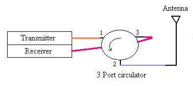
The transmitter connected at port1 can send data using the antenna connected with port 2, and the received data from the antenna is passed to the receiver connected at port3. Hence, due to this functionality of transmission and reception using one antenna, circulators are also referred to as duplexers.
RF or microwave circulators are very essential for RF test and measurement systems. If port 3 is terminated, then the RF circulator becomes an isolator because port 2 to port 1 offers reverse isolation.
Conclusion
In summary, RF circulators are indispensable components designed to enable controlled, unidirectional signal flow and provide efficient signal routing with high isolation between ports. Whether utilized in radar systems, communication networks, or microwave test setups, RF circulators play a crucial role in managing signal paths, minimizing interference, and optimizing the overall reliability and efficiency of diverse applications in the realm of RF technology.
Advertisement


