 RF
RFOp Amp Equations and Formulas
Advertisement
Operational amplifiers (op-amps) are fundamental building blocks in analog electronic circuit design. They are widely used due to their high gain, high slew rate, high Common-Mode Rejection Ratio (CMRR), and other desirable characteristics. Op-amp formulas and equations are crucial for designing, analyzing, and troubleshooting op-amp circuits.
Op Amp Gain
Figure 1 shows the op amp gain for inverting and non-inverting operational amplifiers. As shown, the op amp gain in terms of voltage is the ratio of output to input.
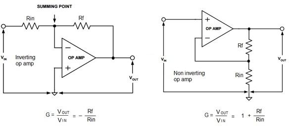
It is expressed as follows:
- op amp gain =
- op amp gain (inverting type) =
- op amp gain (non-inverting type) =
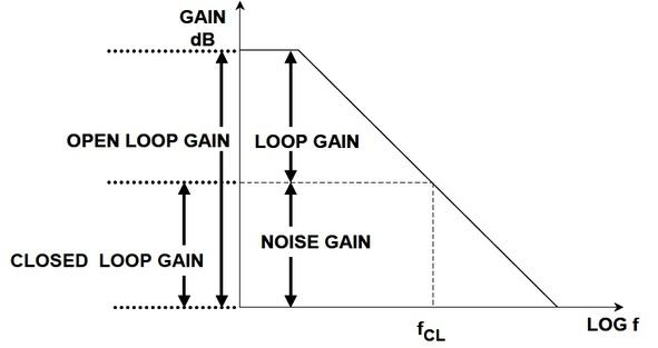
Let’s understand the difference between various op amp gain types, such as closed-loop gain, open-loop gain, signal gain, loop gain, and noise gain. Signal gain is the same as mentioned in the above op amp equations.
Noise gain for both inverting and non-inverting op amps is expressed as follows:
- Noise gain =
Figure 2 shows a comparison between various op amp gain types. In practice, op-amp gains can be very high, often ranging from tens of thousands to hundreds of thousands.
Higher op amp gain can lead to greater sensitivity to noise and stability issues. Lower gain, on the other hand, might not provide the required signal amplification. Hence, a balance is desired.
Op Amp CMRR
The full form of CMRR is Common-Mode Rejection Ratio. If the signal is applied with equal magnitude to both inputs of the op amp such that the differential input voltage is unaffected, then the output should ideally not be affected as well.
In general, changes in common-mode voltage will produce a change in the output. The op amp CMRR is the ratio of the differential-mode gain to the common-mode gain:
It is often expressed in decibels (dB). A higher CMRR is desirable, as it indicates better rejection of unwanted common-mode signals.
Op Amp Full Power Bandwidth (FPBW)
This represents the maximum output frequency at which slew limiting occurs. It’s expressed as follows:
Where is the peak voltage.
The op amp FPBW should ideally be approximately 5 to 10 times higher than the maximum output frequency to obtain acceptable distortion performance using the op amp circuit. Ideally, this bandwidth would be infinite, indicating that the op-amp can handle signals of any frequency without distortion. However, in practice, op-amps have limited bandwidth due to internal limitations. For high-frequency applications, a higher bandwidth is preferable.
Op Amp Slew Rate Formula
The slew rate represents the rate of change in the output voltage with respect to time for a step change at the input of the op amp. It’s expressed as V/s or V/µs. Typically, op amps will have different slew rates during the negative and positive transitions.
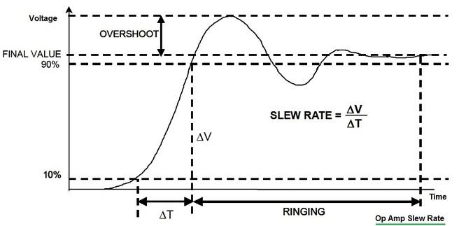
Let’s assume a sine wave with an amplitude of and a frequency :
The maximum slew rate for this is expressed as:
The slew rate is generally measured between 10% and 90% of the final value.
In practice, the slew rate of an op amp should be high so that the op-amp can respond to rapid changes in the input signal, such as in high-frequency applications or pulse amplification.
Advertisement


