VSAT Block Diagram: Operation and Subsystem Functions
Advertisement
A VSAT (Very Small Aperture Terminal) system is designed to provide communication via satellite, typically used in remote or rural areas where traditional communication infrastructure is not available. It enables reliable data, voice, and video transmission for various applications such as broadband Internet, private network services, and remote monitoring.
The VSAT terminal consists of several subsystems, each playing a vital role in the overall operation.
Below is a detailed explanation of the VSAT block diagram and the functions of each subsystem: A VSAT terminal is composed of communication equipment and a small antenna with a diameter of about 3.5 or 4.5 meters.
Typically, VSAT installation requires the following items:
- Outdoor Unit (RF Transceiver, RF LNA, RF Power Amplifier, Antenna, OMT (Orthomode transducer) feed horn)
- Indoor Unit (Satellite modem, MUX, telephone or data connection interface cards)
- Link cable between indoor and outdoor units.
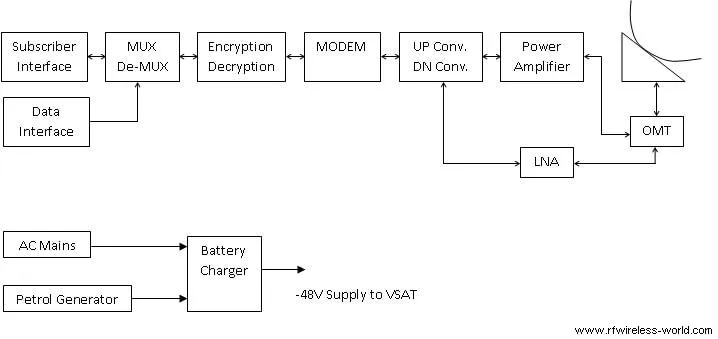
Figure depicts VSAT terminal block diagram.
Here, the MUX acts as a baseband interface for FAX, Data terminal, telephone, etc.
A VSAT terminal is part of a larger network which is managed by a Hub station at a central location. It has all the intelligence to operate, maintain, and configure all the VSAT terminals. Customer database is maintained at the Hub station for billing purposes. The Hub station is also like a VSAT terminal. It houses RF equipment, VSAT interface circuitry, user interfaces, etc.
Let’s understand VSAT terminal operation:
- VSAT is a two-way communication system, and hence one frequency pair (or two frequencies) are needed for establishing a connection. It is also referred to as duplex communication.
- Modern VSATs use FDMA/TDMA/CDMA/DAMA-based access techniques for communication.
- The VSAT terminal is broadly classified into a baseband part and an RF part.
- The baseband part consists of a modem (modulator, demodulator), EDU (Encryptor, Decryptor), Mux/Demux, and data/voice connection circuitry.
- The RF part consists of an antenna, RF Power amplifier, RF LNA, frequency converters (up converter and down converter).
Following are the functions performed by VSAT subsystems in the transmission path:
- The digital data from the user’s device is sent to the modem, where it is modulated into an IF (Intermediate Frequency) signal.
- The IF signal is sent to the BUC (Block Upconverter) via the interconnecting cable. The BUC converts the IF signal to the desired RF (Radio Frequency) frequency and amplifies it.
- The RF signal is then transmitted to the feed horn and directed by the parabolic dish to the satellite in the sky.
Following are the functions performed by VSAT subsystems in the reception path:
- The satellite receives the signal and retransmits it back to the ground station or another VSAT terminal.
- The LNB (Low Noise Block downconverter) captures the RF signals from the satellite, amplifies them, and downconverts them to an IF signal.
- The IF signal is sent to the modem in the IDU (Indoor Unit), where it is demodulated back into digital data for the user.
VSAT Terminal Vendors
The following table mentions manufacturers or Vendors of VSAT terminal equipment used in VSAT-based networks.
| VSAT Terminal manufacturers or vendors |
|---|
| Viasat |
| Vizocom |
| Satellite Engineering Group, Singapore |
| Paradise, UK |
| Mitec Telecom Direct |
| Hughes Network Systems |
| Gilat |
| Comtech EF Data, USA |
| Comsys, UK |
| Codan, Australia |
| Avsatcom |
Conclusion
The operation of the VSAT system involves the integration of these subsystems to provide seamless two-way communication via satellite links. This setup allows VSAT to support a wide range of applications, such as Internet access, corporate intranets, SCADA (Supervisory Control and Data Acquisition), and video conferencing, making it an essential tool for connecting remote and underserved locations.