Raised Cosine vs Root Raised Cosine Filters: Key Differences
Advertisement
This article explains the difference between the Raised Cosine Filter and the Root Raised Cosine Filter. We will delve into their impulse response functions and related plots. As we know, filters play a crucial role in removing unwanted frequency components from a signal.
Digital data bits, when represented in the time domain, resemble square waves. These waves contain numerous harmonic components. Due to this, Radio Frequency (RF) specifications, such as the Adjacent Channel Leakage Ratio (ACLR), might not meet the required standards. Therefore, these filters are employed to process baseband digital data before it’s coupled with the RF section (i.e., the RF Transceiver). Using these filters, the shape of the data bits becomes smoother, significantly reducing harmonic content.
Raised Cosine Filter
The following image shows the impulse response of a Raised Cosine Filter:
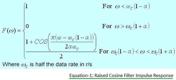
The impulse response of a Raised Cosine Filter can be mathematically realized using Equation 1 (not provided in the original article, so I’ll refrain from adding a placeholder equation). The result is plotted as shown in the figure above.
Ideally, the Raised Cosine Filter response exhibits unity gain at lower frequencies. It provides complete attenuation at higher frequencies. The frequency response in the middle section follows a raised cosine function.

The width of this middle part is governed by Alpha (), also known as the roll-off factor. Alpha typically ranges from 0 to 1. The passband of the filter is defined by the points where the signal attenuation reaches 50%.
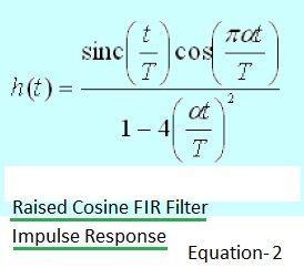
There are various types of filters, including Infinite Impulse Response (IIR) filters, analog filters, and Finite Impulse Response (FIR) filters. FIR filters are often favored for their ease of implementation. For a comparison, refer to resources detailing the difference between FIR and IIR filters.
Equation 2 (again, not provided in original article) would help realize a Raised Cosine FIR filter impulse response. Higher-order filters result in a more refined raised cosine shape, but this comes at the cost of increased delay.
Root Raised Cosine Filter
The image below illustrates the impulse response of a Root Raised Cosine Filter:
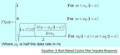
The impulse response of the Root Raised Cosine Filter is determined by Equation 3 (equation not provided). The corresponding frequency response is plotted in the following figure:
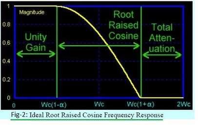
The response is similar to the standard Raised Cosine Filter, but exhibits a steeper transition in the middle section. This response follows the square root of the function described in Equation 1.
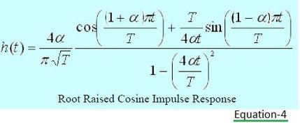
Equation 4 is used to realize the root raised cosine FIR filter frequency response. When employing a Root Raised Cosine Filter, one part is used at the transmitter, and a similar part is used at the receiver.
MATLAB Functions
The following MATLAB function returns coefficients (b) for the filter types discussed:
b = rcosdesign(beta,span,sps,shape)
Shape = 'sqrt'returns coefficients as per square-root raised cosine FIR filter.Shape = 'normal'returns coefficients as per raised cosine FIR filter.
Advertisement
 RF
RF


