LTE Reference Signals: RS, DMRS, and SRS Explained
Advertisement
This page describes LTE downlink reference Signal (RS), uplink reference signals viz. sounding reference signal (S-RS) and Demodulation reference signal (DM-RS) used in LTE.
Downlink Reference Signal

The downlink reference signal in LTE corresponds to a set of resource elements used by the physical layer but does not carry any higher layer’s information. To allow for coherent demodulation at the user equipment, reference symbols (or pilot symbols) are inserted in the OFDM time-frequency grid to allow for channel estimation.

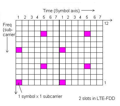
Two downlink RSs are inserted within the first and third from last OFDM symbol of each slot. Both of them will have frequency domain spacing of six sub carriers within the same symbol as shown in the figure. This is with LTE system having one antenna in normal CP mode.
Furthermore, there is a frequency domain staggering of 3 subcarriers between the first and second RSs (reference symbols). In total, there are four RSs (reference symbols) in each Resource Block. UE interpolates over multiple reference symbols to estimate the channel.
For 2 transmit antenna system, RSs are inserted from each antenna where the RSs on the second antenna are offset in the frequency domain by 3 subcarriers. To allow the UE to accurately estimate the channel coefficients, nothing is transmitted on the other antenna port at the same time & frequency location of RSs.
There are total 510 RS sequences which corresponds to 510 different and unique cell identities. The RSs are derived from the product of a two-dimensional pseudo-random sequence and a two-dimensional orthogonal sequence:
- 170 pseudo-random sequences corresponding to cell-identity groups
- 3 orthogonal sequences each corresponding to a specific cell identity within the cell identity group.
Uplink Physical Reference Signals

Uplink physical reference signals are used within the PHY layer and do not convey information from higher layers. There are two main types sounding reference signal and demodulation reference signal as mentioned below.
Demodulation reference signal
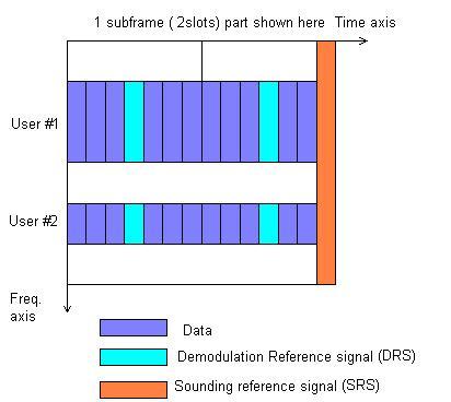
This facilitates coherent demodulation and associated with transmission of PUSCH or PUCCH. It is transmitted in the fourth SC-FDMA symbol of the slot and is the same size as the assigned resource.
Sounding reference signal
This is used to facilitate frequency dependent scheduling and not associated with transmission of PUSCH or PUCCH. Both variants of the UL reference signal are based on Zadhoff Chu sequences. SRS are of two types based on periodicity.The min. periodicity of SRS is 2ms and the max. about 320ms.
The similarity between SRS and DMRS is that both of them use CAZAC sequences (Constant Amplitude Zero Autocorrelation sequences).
| Reference signal type | Direction | Modulation | Position | Function |
|---|---|---|---|---|
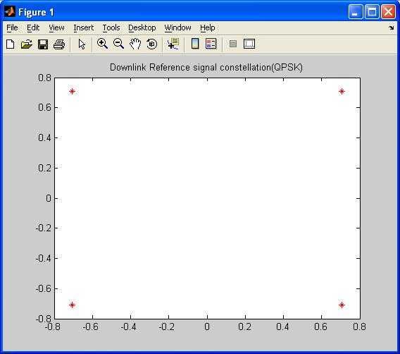
| DL-RS | Downlink | QPSK | 1st and 3rd from last OFDM symbol in each slot, 6 subcarrier difference between them in the symbol | These pilot subcarriers are used for channel estimation by UE |
| DM-RS | Uplink | fourth SC-FDMA symbol of the slot | Channel estimation | |
| SRS | Uplink | Zadoff Chu | transmitted on last SC-FDMA symbol of each subframe or once after 2 slots | channel estimation |
Advertisement
 RF
RF
