Hybrid Beamforming: Basics and Types Explained
Advertisement
This article explains the fundamentals of hybrid beamforming and its different types. It compares two main types: partially connected and fully connected hybrid beamforming. It also discusses the advantages and disadvantages of each type. Furthermore, it differentiates between the architectures of analog beamforming, digital beamforming, and hybrid beamforming.
Introduction:
Beamforming aims to achieve directional signal transmission and reception, along with power control. This is made possible by varying the amplitude and phase in the beamforming system. Antenna arrays, with provisions for amplitude/phase variation, are used for this purpose.
The main types of beamforming are:
- Analog Beamforming
- Digital Beamforming
- Hybrid Beamforming
Before diving into hybrid beamforming, let’s understand the core concepts used in analog and digital beamforming.
Analog Beamforming
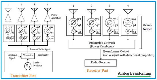
In analog beamforming, amplitude/phase variation is applied to the analog signal at the transmitting end. At the receiving end, the signals from different antennas are summed before Analog-to-Digital Conversion (ADC). Figure 1 illustrates the transmitter and receiver components used in analog beamforming.
Mathematical Equations:
- Wk = ak * ejsin(θk)
- Wk = ak *cos(θk) + j _* ak sin(θk)
Where:
- Wk represents the complex weight for the kth antenna in the array.
- ak is the relative amplitude of the weight.
- θk is the phase shift of the weight.
Weights are applied to analog signals in analog beamforming. For a block diagram-based explanation of analog and digital beamforming, refer to Analog beamforming vs. Digital beamforming. As mentioned, weights are applied to the analog signal at RF or IF frequencies. It is restricted to one RF chain even with a large number of antenna arrays.
Digital Beamforming
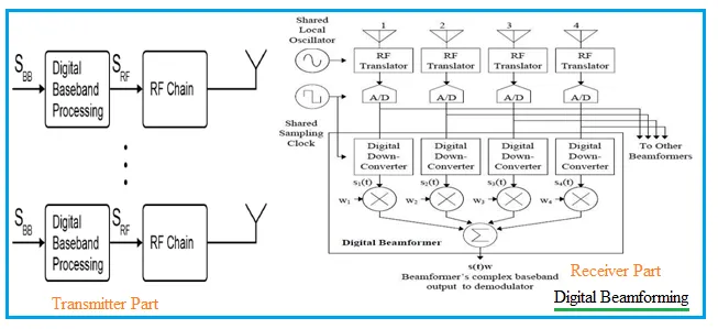
In digital beamforming, amplitude/phase variation (Wk) is applied to the digital signal after ADC/Digital Down Conversion (DDC) at the transmitting end. At the receiving end, the signals from the antennas are first passed through ADCs and DDCs before summation. Figure 2 shows the transmitter and receiver parts used in digital beamforming.
Mathematical Equations:
- s(t) = x(t) + j * y(t)
Where:
- s(t) -> complex baseband signal
- x(t) -> i(t) (real part, I)
- y(t) -> -q(t) (imaginary part, Q)
- j = SQRT(-1)
Complex weights are applied to baseband signals (s(t)) in digital beamforming. Unlike analog beamforming, digital beamforming supports multiple RF chains proportional to the antenna elements in use. Here, beamforming or precoding is applied to the digital baseband signal.
What is Hybrid Beamforming?
This type of beamforming combines the advantages of both analog and digital beamforming, hence the name “hybrid.” Precoding is applied in both the analog and digital domains, meaning it employs precoding/beamforming at both Radio Frequency (RF) and baseband. This makes it suitable for millimeter wave radio-based next-generation mobile networks, including 5G.
Hybrid Beamforming Types | Advantages and Disadvantages
The two main types of hybrid beamforming are:
- Partially Connected Hybrid Beamforming (HB)
- Fully Connected Hybrid Beamforming
Partially Connected Hybrid Beamforming
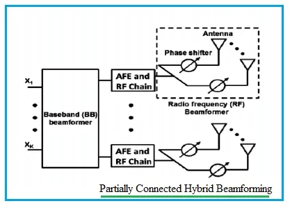
Figure 3 illustrates the partially connected HB type. This architecture uses a separate antenna array (referred to as a “sub-array”) for the RF beamformer of each individual AFE/RF chain. Due to this architecture, it is also known as sub-array hybrid beamforming.
Fully Connected Hybrid Beamforming
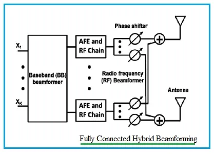
Figure 4 depicts the fully connected HB type. In this architecture, the RF beamformer of each AFE/RF chain utilizes all the antennas. The RF signals from different AFE/RF chains are combined before transmission through the antenna. This is done for each antenna in the system, leading to the alternative name “full-array hybrid beamforming.”
Advantages and Disadvantages:
In fully connected architectures, the additional components used to combine RF signals can lead to signal attenuation and power losses, posing a challenge in mmWave radio systems. Partially connected architectures, on the other hand, limit AFE/RF chain access to fewer antennas. This can lead to wider beamwidths, less directivity, and stronger interference from other chains.
Despite these disadvantages, advanced MIMO techniques can help mitigate interference in partially connected hybrid beamforming. Moreover, the partially connected architecture offers simpler circuit design and fewer losses compared to the fully connected architecture.
The choice of architecture depends on the application, hardware and software complexities, and available technologies. Reconfigurable hybrid beamforming is also evolving to leverage many benefits in single-user MIMO-based systems.
This introductory note on hybrid beamforming will help you understand the different beamforming types and their architectures. For more information, refer to technology/standard-specific design aspects.