 RF
RFGTO vs IGCT vs IGBT: A Detailed Comparison
Advertisement
This article compares Gate Turn-Off Thyristors (GTOs), Insulated Gate Commutated Thyristors (IGCTs), and Insulated Gate Bipolar Transistors (IGBTs). We’ll explore the differences between these three power semiconductor devices in terms of their symbols, characteristics, advantages, disadvantages, and applications.
GTO (Gate Turn-Off Thyristor)
GTOs are thyristors with the ability to be turned off by a gate signal.
 Figure 1: GTO construction and symbol
 Figure 2: GTO base unit and its two transistor equivalent model
 Figure 3: Voltage and current waveforms during GTO turn-off
IGCT (Insulated Gate Commutated Thyristor)
IGCTs are another type of thyristor that utilizes a gate signal to turn off, but with an improved gate structure.
 Figure 4: IGCT circuit symbol
 Figure 5: IGCT structure
 Figure 6: Voltage and current waveforms during IGCT turn-off
IGBT (Insulated Gate Bipolar Transistor)
IGBTs are a hybrid device combining the advantages of MOSFETs and BJTs.
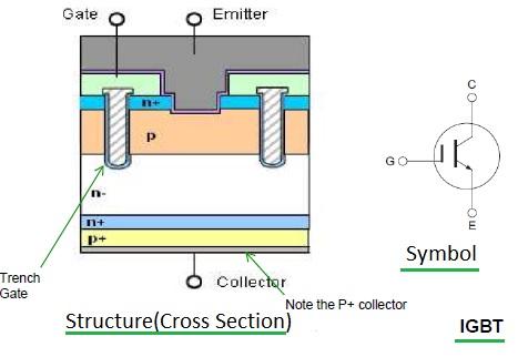 Figure 7: IGBT structure and symbol
The key difference between the two structures lies in the addition of a p-substrate below the n-substrate in the IGBT.
 Figure 8: IGBT output characteristics
For a deeper understanding, refer to a comparison of MOSFETs vs. IGBTs.
GTO vs IGCT vs IGBT: Comparison Table
The following table summarizes the key differences between GTOs, IGCTs, and IGBTs:
| Specifications | GTO | IGCT | IGBT |
|---|---|---|---|
| Full Form | Gate Turn-Off Thyristor | Insulated Gate Commutated Thyristor | Insulated Gate Bipolar Transistor |
| Advantages | • Controlled turn-off ability. | • Controlled turn-off ability. | • Controlled turn-off ability. |
| • Relatively high overload capacity. | • Relatively high overload capacity. | • Minimum working frequency up to 10 kHz. | |
| • Series connection possibility. | • Low on-state losses. | • Very low control power. | |
| • Working frequency of hundreds of Hz. | • Working frequency of kHz. | ||
| • Series connection possibility. | |||
| • High cyclic resistance. | |||
| Disadvantages | • Higher on-state losses. | • Very high on-state losses. | |
| • High control power. | • Relatively low cyclic resistance. | ||
| Applications | • High power drives | • High power drives | • Switching sources |
| • Static compensators | • Supply inverter sources for DC transmissions | • Statical compensators and active filters | |
| • Continuous supply sources | • Big frequency converters | • Continuous supply sources | |
| • Induction heating sources | • Choppers |
Key Takeaways: IGCT vs. IGBT
Here’s a quick summary of the useful comparisons between IGCTs and IGBTs:
- Switching Frequency: IGBTs boast a significantly higher switching frequency compared to IGCTs.
- Lifespan: IGBTs generally have a lifespan ten times greater than that of IGCTs.
- On-State Voltage Drop: IGCTs exhibit a lower ON-state voltage drop.
- Construction & Cooling: IGCTs are typically constructed as disk devices, which can lead to increased electromagnetic emissions and cooling challenges.
Advertisement


